
Integrated floor mounting structure and mounting process thereof

An installation structure and integrated technology, applied in the direction of building structure, floor, insulation layer, etc., can solve the problems of lack of adaptability, easy to damage the floor, and affect the appearance, so as to improve the comfort of use, prevent the floor from warping, The effect of improving the waterproof effect

Pending Publication Date: 2020-03-31
安徽山水空间装饰股份有限公司
View PDF1 Cites 0 Cited by
  • Summary
  • Abstract
  • Description
  • Claims
  • Application Information

AI Technical Summary

Problems solved by technology

[0003] However, there are still relatively obvious defects in its use: 1. The height of the support in the above-mentioned device is fixed, so the installation height of the floor cannot be adjusted, but due to reasons such as unevenness of the plane, it is often necessary to The height of the floor is independently fine-tuned to make up for the difference in height. The above-mentioned device obviously lacks adaptability and has high requirements for the flatness of the installation plane; 2. Water seepage is very easy to occur in the gaps between the floors, and the above-mentioned device cannot play an effective waterproof role , so that after a long time of use, the floor will be warped due to being soaked in water, which will not only affect the appearance, but also cause potential safety hazards; 3. The overall structure and joints of the above-mentioned floors are all hard materials, while the floor Thermal expansion and contraction will occur due to temperature changes. The above-mentioned device cannot effectively buffer the variation range of thermal expansion and contraction of the floor, and it is easy to damage the floor

Method used


Image

  • Integrated floor mounting structure and mounting process thereof
  • Integrated floor mounting structure and mounting process thereof
  • Integrated floor mounting structure and mounting process thereof

Examples


Embodiment Construction

[0027] The following will clearly and completely describe the technical solutions in the embodiments of the present invention with reference to the accompanying drawings in the embodiments of the present invention. Obviously, the described embodiments are only some, not all, embodiments of the present invention. Based on the embodiments of the present invention, all other embodiments obtained by persons of ordinary skill in the art without making creative efforts belong to the protection scope of the present invention.

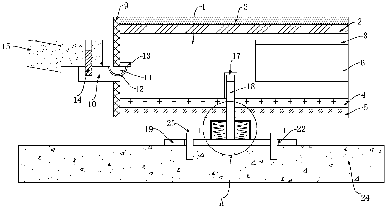
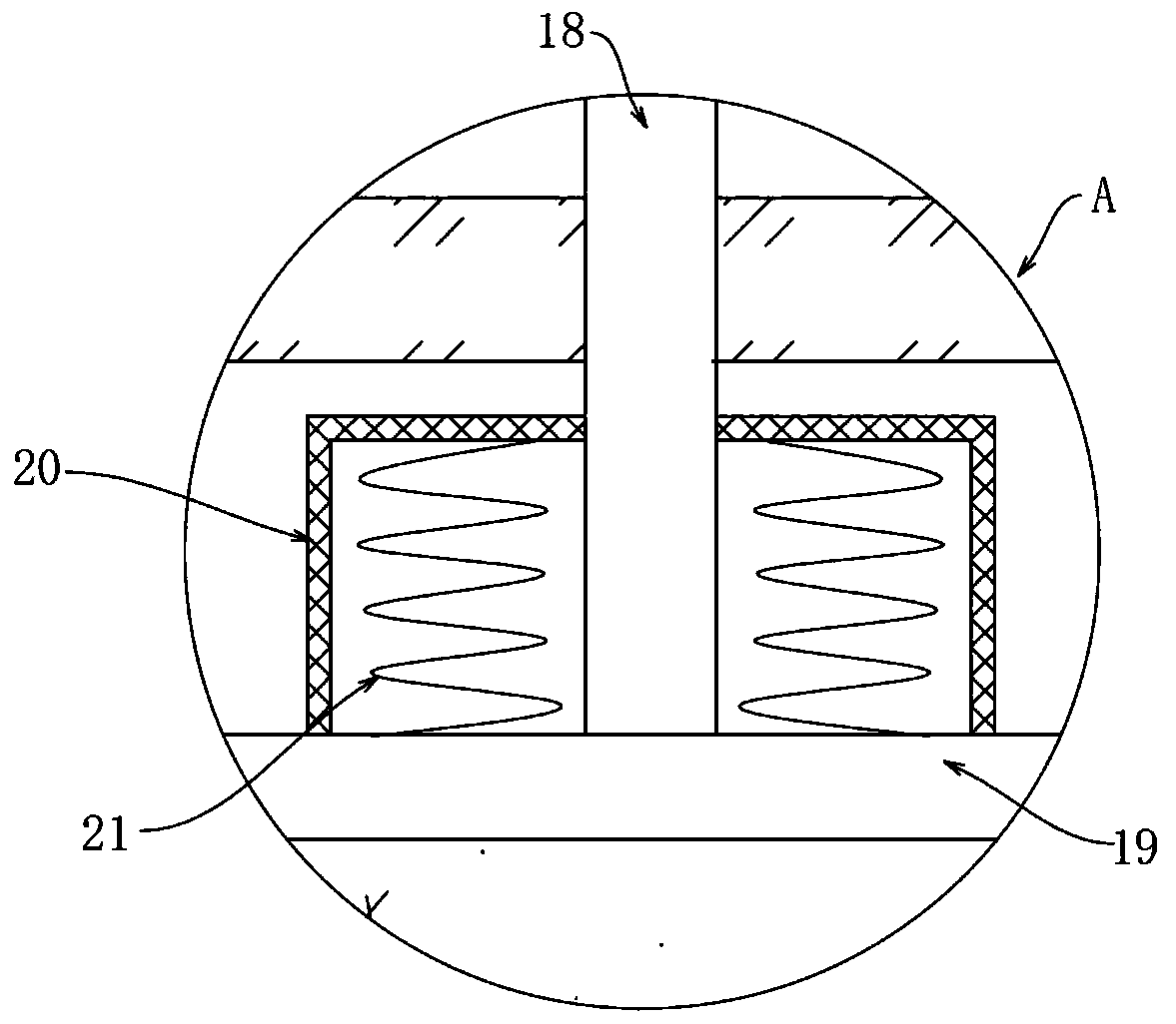
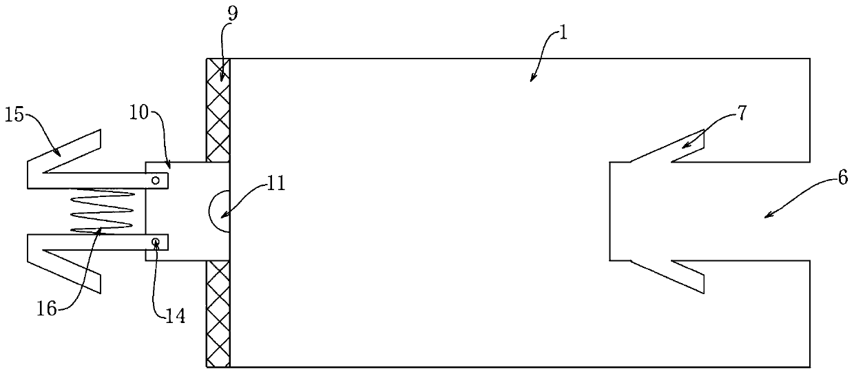
[0028] see Figure 1-4 , the present invention provides a technical solution:

[0029] An integrated floor installation structure, including a floor body 1, the upper surface of the floor body 1 is provided with a sound insulation layer 2, which plays the role of noise reduction, and the lower surface of the floor body 1 is provided with a heat insulation layer 4, which reduces heat conduction and heat insulation A shock-absorbing layer 5 is arranged below th...


PUM


Abstract

The invention discloses an integrated floor mounting structure and a mounting process thereof. The integrated floor mounting structure comprises a floor body, wherein a clamping groove is formed in one side of the floor body; oblique limiting grooves are symmetrically formed in the positions, on the two sides of the clamping groove, of the floor body; two elastic sealing pads are arranged on the side, away from the clamping groove, of the floor body; a water-resistant coating is arranged in an arc-shaped groove; a compression spring is connected between two sets of clamping rods; a telescopicelastic pipe is arranged on the side, close to a threaded rod, of a mounting bottom plate; a damping spring is arranged in the telescopic elastic pipe; a fixing threaded hole is formed in the mountingbottom plate; and a fixing screw is arranged in a base surface. According to the integrated floor mounting structure, the requirement for the flatness of the mounting base surface is not high, the height of a supporting piece can be independently adjusted, the waterproof effect is good, and no gap exists at the splicing position; and the invention further provides the mounting process based on the integrated floor mounting structure, operation is easy, and the integrated floor mounting structure and the mounting process are very worthy of popularization.

Description

technical field [0001] The invention relates to the technical field of integrated floors, in particular to an integrated floor installation structure and an installation process thereof. Background technique [0002] In the prior art, the installation structure of an integrated floor with the application number "201910409156.8" includes a plurality of floor units installed on the ground base. Several supports are arranged between the floor units and the ground base. The supports are The cross-section is an I-shaped support member, which forms two symmetrically arranged support cavities, and the elastic support bar is fixed in the support cavity. The installation structure can effectively reduce the impact of heavy objects or stepping on the support, and can achieve a more stable support for the floor under the premise of low cost. [0003] However, there are still relatively obvious defects in its use: 1. The height of the support in the above-mentioned device is fixed, so ...

Claims


Application Information

Patent Timeline
IPC IPC(8): E04F15/02E04F15/18E04F15/20
CPCE04F15/02E04F15/02016E04F15/18E04F15/203
Inventor 宋春红房珺鲍晓霖
Owner 安徽山水空间装饰股份有限公司
Learn More