
MEMS inertial measurement unit automatic calibration system and calibration verification method thereof

A technology of inertial measurement unit and micro-electro-mechanical system, which is applied in the field of micro-electro-mechanical systems, can solve the problems of cumbersome and time-consuming processes and low efficiency

Active Publication Date: 2022-03-08
NAT INST OF METROLOGY CHINA
View PDF12 Cites 0 Cited by
  • Summary
  • Abstract
  • Description
  • Claims
  • Application Information

AI Technical Summary

Problems solved by technology

Traditional MEMS IMU calibration requires manual operation of the industrial computer to control the movement of the turntable, data acquisition and storage also require special operations, the whole process is tedious, time-consuming, and inefficient

Method used


Image

  • MEMS inertial measurement unit automatic calibration system and calibration verification method thereof
  • MEMS inertial measurement unit automatic calibration system and calibration verification method thereof
  • MEMS inertial measurement unit automatic calibration system and calibration verification method thereof

Examples


Embodiment 1

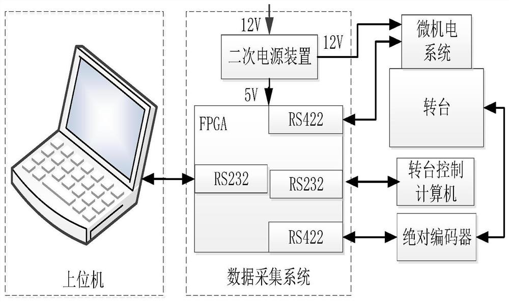
[0053] See attached figure 1 , the MEMS inertial measurement unit automatic calibration system provided by Embodiment 1 of the present invention includes:

[0054] The host computer is used to issue turntable control commands;

[0055] The data acquisition system, including the minimum system circuit based on FPGA, is used to collect the data output by the MEMS inertial test unit to be calibrated and the feedback data of the turntable, and transmit the data output by the MEMS inertial test unit and the feedback data of the turntable in real time Send to the turntable control computer;

[0056] The turntable control computer is used to control the turntable according to the turntable control command obtained from the data acquisition system;

[0057] A turntable, a MEMS IMU to be calibrated, used as a calibration target for the MEMS IMU automatic calibration system;

[0058] Absolute encoder, used to obtain the absolute angular position information of the turntable.

[0059...

Embodiment 2

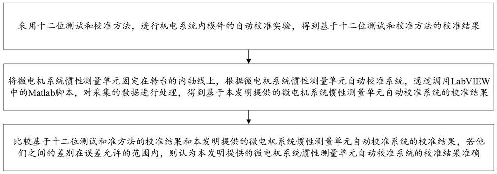
[0069] See attached figure 2 The calibration verification method of the MEMS inertial measurement unit automatic calibration system provided by the second embodiment of the present invention includes the following steps:

[0070] Step S1: Using the 12-bit test and calibration method, conduct an automatic calibration experiment of the modules in the electromechanical system, and obtain the calibration result based on the 12-bit test and calibration method;

[0071] Step S2: Fix the MEMS inertial measurement unit on the inner axis of the turntable, automatically calibrate the system according to the MEMS inertial measurement unit, and process the collected data by calling the Matlab script in LabVIEW to obtain the system based on the present invention. Calibration results of the MEMS inertial measurement unit automatic calibration system;

[0072] Step S3: Compare the calibration results based on the twelve-bit test and quasi-method with the calibration results of the MEMS IMU...


PUM


Abstract

Disclosed are an automatic calibration system for a micro-electromechanical system inertial measurement unit and a calibration verification method thereof. The system includes a host computer, which is used to issue control commands for the turntable; a data acquisition system, including a minimum system circuit based on FPGA, which is used to collect the output data of the MEMS inertial test unit to be calibrated and the feedback data of the turntable, and transfer the MEMS The data output by the system inertial test unit and the feedback data of the turntable are sent to the turntable control computer in real time; the turntable control computer is used to control the turntable according to the turntable control command obtained from the data acquisition system; the turntable is to be calibrated MEMS inertial measurement The unit is used for the calibration target of the MEMS inertial test unit automatic calibration system; the absolute encoder is used to obtain the absolute angular position information of the turntable. The verification method can verify whether the calibration result of the calibration system is accurate. It can automatically complete the calibration task of the modules in the micro-electro-mechanical system, and can improve the calibration efficiency.

Description

technical field [0001] The invention relates to the technical field of micro-electro-mechanical systems, in particular to an automatic calibration system for an inertial measurement unit of a micro-electro-mechanical system and a calibration verification method thereof. Background technique [0002] The MEMS IMU is mainly composed of inertial sensors, including gyroscopes and accelerometers. The measurement accuracy of the inertial sensor and the deterministic error of the inertial measurement unit during the mechanical structure design and assembly process largely determine the navigation accuracy. MEMS inertial measurement unit calibration experiments include multi-position static calibration and multi-rate dynamic calibration. Traditional MEMS IMU calibration requires manual operation of the industrial computer to control the movement of the turntable, and special operations are also required for data acquisition and storage. The whole process is tedious, time-consuming,...

Claims


Application Information

Patent Timeline
Patent Type & Authority Patents(China)
IPC IPC(8): G01C25/00
CPCG01C25/005
Inventor 叶文蔡晨光刘志华夏岩
Owner NAT INST OF METROLOGY CHINA
Learn More