An Improved Embedded Concrete Strain Gauge

A strain gauge, concrete technology, applied in the field of bridge structure stress monitoring, can solve the problems of concrete strain gauge reading error, concrete strain gauge difficulty, unreasonable and so on

Active Publication Date: 2021-07-06
WUHAN UNIV OF TECH
View PDF5 Cites 0 Cited by
  • Summary
  • Abstract
  • Description
  • Claims
  • Application Information

AI Technical Summary

Problems solved by technology

The traditional concrete strain gauge considers the steel bar of the measured structure as a smooth round steel bar, but the stressed longitudinal bar in the actual construction monitoring is a ribbed steel bar, so there is only a point-to-point contact between the ribbed steel bar and the traditional concrete strain gauge. It is impossible to ensure good adhesion between the ribbed steel bar and the concrete strain gauge, and to transmit the actual deformation. At the same time, the thickness of the stress handle of the concrete strain gauge is relatively large for the distance between the diagonal rib of the ribbed steel bar and the horizontal direction, resulting in the force handle It acts on the diagonal ribs of the ribbed steel bars, not between the ideal diagonal ribs; considering the actual operating environment of construction monitoring, the installation of concrete strain gauges is not ideally fixed directly below the stressed longitudinal reinforcement, and the wire binding The direction of the wire is not ideally perpendicular to the concrete strain gauge. At the same time, it is easy to cause the wire to slip, causing some wire to jump out of the end seat and bind it to the casing, resulting in an error in the reading of the concrete strain gauge. At the same time, due to the narrow actual operating environment of construction monitoring, As a result, it is difficult for a single person to install the concrete strain gauge, and when only one end seat of the concrete strain gauge is fixed, it is easy to cause the action position of the other end end seat to not be directly under the stressed longitudinal reinforcement, resulting in unsatisfactory deformation measured later Deformation, unreasonable error

Method used


Image

  • An Improved Embedded Concrete Strain Gauge
  • An Improved Embedded Concrete Strain Gauge
  • An Improved Embedded Concrete Strain Gauge

Examples


Embodiment Construction

[0023] In order to make the object, technical solution and advantages of the present invention more clear, the present invention will be further described in detail below in conjunction with the examples. It should be understood that the specific embodiments described here are only used to explain the present invention, not to limit the present invention.

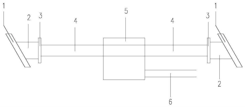
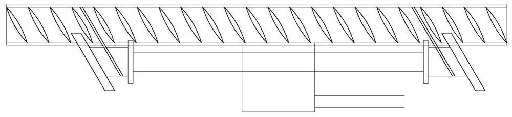
[0024] like figure 1 and figure 2 As shown, an improved embedded concrete strain gauge mainly includes: a stress handle 1, an end seat 2, an inner plate of the end seat 3, a casing 4, an electronic component 5, and a wire 6.

[0025] An improved embedded concrete strain gauge, comprising: a strain gauge body and a mount part;

[0026] The strain gauge body includes: a protective sleeve 4, a wire 6, and an electronic component 5. The electronic component is sleeved on the protective sleeve, and the wire is arranged outside the protective tube to connect with the electronic component; both ends of the protective sleeve are...


PUM


Abstract

The invention discloses an improved embedded concrete strain gauge. The strain gauge comprises: a strain gauge body and a mounting seat part; the strain gauge body comprises: a protective casing, a wire, and an electronic component, and the electronic component is sheathed in the protective cover The wires are arranged outside the protective tube to connect with the electronic components; both ends of the protective sleeve are provided with a mounting seat part, which in turn includes an end seat and a stress handle, and the end of the stress handle in contact with the ribbed steel bar An arc-shaped groove adapted to the steel bar column is arranged on the upper part, and several grooves for engaging with the straight rib are arranged on the surface of the arc-shaped groove. The present invention proposes an improved embedded concrete strain gauge, which not only takes into account the shape of the ribbed steel bar, the inclination angle of the diagonal rib, the existence of the straight rib, and the direction of the steel bar, but also considers the installation and fixation of the concrete strain gauge during installation. , the present invention greatly reduces errors caused by installation problems, and at the same time reduces installation difficulty in construction monitoring.

Description

technical field [0001] The invention relates to bridge structure stress monitoring technology, in particular to an improved embedded concrete strain gauge. Background technique [0002] With the rapid development of infrastructure construction, bridges, as an important part of infrastructure, have also developed rapidly. In the construction of bridges, there are more and more large bridges. In order to ensure the construction safety and smooth closure of large bridges , Conforming to the design alignment, construction monitoring plays a vital role; in construction monitoring, stress monitoring is an important part, and the accuracy of stress monitoring has a great relationship with the monitoring instruments. [0003] At present, the traditional concrete strain gauges used in construction monitoring have many problems with the actual situation on site. The traditional concrete strain gauge considers the steel bar of the measured structure as a smooth round steel bar, but th...

Claims


Application Information

Patent Timeline
Patent Type & Authority Patents(China)
IPC IPC(8): G01L1/00E01D21/00E01D101/24
CPCE01D21/00E01D2101/24G01L1/00
Inventor 康俊涛冯毅
Owner WUHAN UNIV OF TECH
Why Eureka
Try Eureka