Double-cantilever differential fiber grating current transformer

A technology of current transformer and fiber grating, applied in the direction of measuring current, voltage/current isolation, measuring current/voltage, etc., can solve the problem that the detection accuracy is easily affected by the ambient temperature, and the detection accuracy of fiber grating current transformer is low in reliability. and other problems to achieve the effect of improving detection reliability and reducing impact.

Inactive Publication Date: 2020-03-31
DATONG POWER SUPPLY COMPANY OF STATE GRID SHANXI ELECTRIC POWER
View PDF2 Cites 2 Cited by
  • Summary
  • Abstract
  • Description
  • Claims
  • Application Information

AI Technical Summary

Problems solved by technology

[0004] In the existing technology, fiber grating current transformers are usually used instead of electromagnetic sensors. Although the problems of electromagnetic sensors can be solved, the detection accuracy is easi

Method used


Image

  • Double-cantilever differential fiber grating current transformer
  • Double-cantilever differential fiber grating current transformer
  • Double-cantilever differential fiber grating current transformer

Examples


Embodiment 1

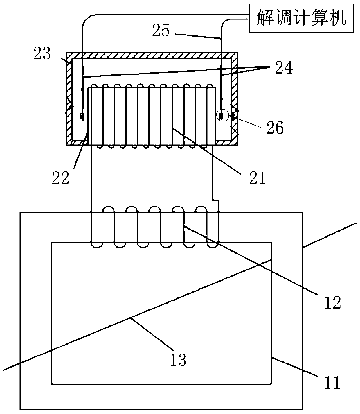
[0022] Such as figure 1 As shown, this embodiment provides a double cantilever beam differential fiber grating current transformer, the current transformer is suitable for cable sheath ground current detection, the current transformer includes: a first sensing unit, a second sensing unit and demodulation computer;

[0023] The first induction unit comprises a magnetizer 11 and a first induction coil 12, the magnetizer 11 is a hollow rectangle, and the first induction coil 12 is wound on a lateral side of the magnetizer 11; the second induction unit comprises a second induction coil 21, an iron The core 22 , the outer support structure 23 and two magnetic deformation units 24 , the second induction coil 21 is wound on the iron core 22 .

[0024] Further, the first induction coil 12 is wound on a lateral side of the magnetizer 11 in a clockwise direction, and the second induction coil 21 is wound on the iron core 22 in a counterclockwise direction; the magnetic field lines of t...

Embodiment 2

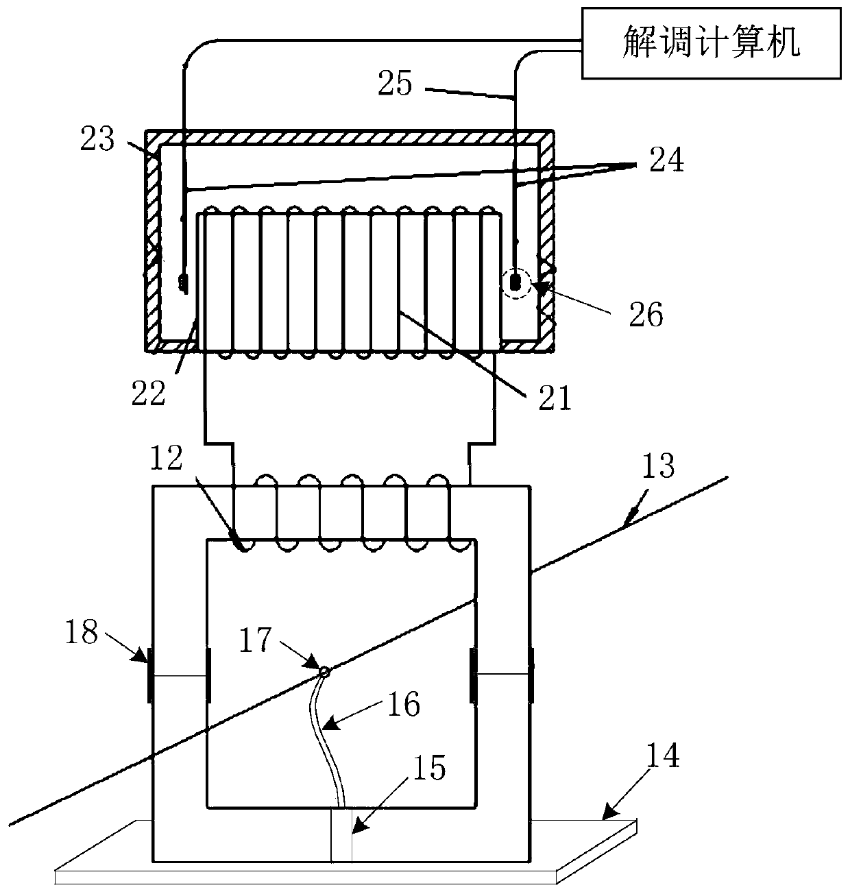
[0033] Such as figure 2 As shown, this embodiment provides another double-cantilever beam differential fiber grating current transformer. In order to further reduce the cost of current detection, the main detection part is set as a split structure, so that the same current carrying capacity When detecting the grounding current of the cable sheath of a different cable, the same set of current transformers can be used to avoid the difference between the detection devices, resulting in abnormal detection results.


PUM


Abstract

The invention discloses a double-cantilever differential fiber grating current transformer, which is suitable for cable sheath grounding current detection, and comprises a first induction unit including a magnetizer and a first induction coil, the magnetizer is in hollow rectangular shape, and the first induction coil is wound on one transverse edge of the magnetizer;, a second induction unit comprises a second induction coil, an iron core, an outer supporting structure and two magnetic deformation units. The second induction coil is wound around the iron core, and the magnetic deformation units are arranged at the left and right ends of the outer supporting structure, and are fixed in the vertical direction, a magnet is arranged at the top end of each magnetic deformation unit and locatedin the center of the second induction coil, and the magnetic induction lines of the magnets at the top ends of the two magnetic deformation units are opposite in pointing direction; and a demodulation computer is connected to the two magnetic deformation units through optical fiber pigtails. According to the technical scheme, the detection reliability of the fiber bragg grating current transformer is improved, and the influence of environment temperature change on the detection precision of the fiber bragg grating current transformer is reduced.

Description

technical field [0001] The present application relates to the technical field of current transformers, in particular, to a double cantilever beam differential fiber grating current transformer. Background technique [0002] At present, the detection methods for the grounding current of the cable sheath are mostly electromagnetic sensors, which use basic electromagnetic induction elements such as iron cores and inductance coils to realize the detection of the current variable cable sheath grounding current of the line under test. However, electromagnetic sensors have problems such as active installation, short transmission distance, easy interference of signals, and inconvenient parasitic interconnection. [0003] Fiber Bragg grating current transformer can ideally solve the above problems. It uses the characteristics of optical signal transmission so that it does not need to be installed independently, which greatly increases the signal transmission distance and is not easy ...

Claims


Application Information

Patent Timeline
IPC IPC(8): G01R15/24G01R19/00
CPCG01R15/245G01R19/0092
Inventor 赵国伟顾袁洁常波赵海波贾杏平张尧李龙
Owner DATONG POWER SUPPLY COMPANY OF STATE GRID SHANXI ELECTRIC POWER
Why Eureka
Try Eureka