
Charging and discharging module and inductance element thereof

A technology of charging and discharging modules and inductive components, which is applied in the direction of electrical components, charging stations, transformer/inductive components, etc., can solve the problem that the cold plate cannot meet the heat dissipation requirements of inductive components, shorten the heat transfer path, and increase the heat dissipation speed , Improve the effect of cooling efficiency

Active Publication Date: 2020-03-31
XJ POWER CO LTD +2
View PDF8 Cites 1 Cited by
  • Summary
  • Abstract
  • Description
  • Claims
  • Application Information

AI Technical Summary

Problems solved by technology

[0005] The purpose of the present invention is to provide an inductance element, which can solve the problem in the prior art that only relying on the cold plate cannot meet the heat dissipation requirements of the inductance element;

Method used


Image

  • Charging and discharging module and inductance element thereof
  • Charging and discharging module and inductance element thereof
  • Charging and discharging module and inductance element thereof

Examples


Embodiment 2

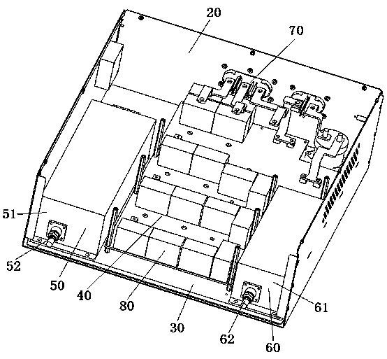
[0074] Embodiment 2 of the charge-discharge module in the present invention: the difference from the above-mentioned embodiment is that the installation shell in this embodiment only includes side walls arranged vertically on the cold plate, and the side walls are connected to each other to form the installation shell. frame structure. At this time, the potting compound fixes the coil in the installation shell by adhering to the side wall. Each side wall is provided with a refrigerant flow channel, and the refrigerant flow channels in adjacent side walls are connected. The side walls enclose the coil laterally, and the bottom of the coil is directly in contact with the cold plate. At this time, a cooling flow channel at the bottom of the coil may be provided in the cold plate, and the cooling flow channel communicates with the refrigerant flow channel and shares a cold source.

Embodiment 3

[0075] Embodiment 3 of the charging and discharging module in the present invention: the difference from the above embodiments is that the inlet and outlet of the refrigerant channel in the installation shell in this embodiment are connected to the corresponding interface on the cold plate, and the one connected to the external cold source The total refrigerant inlet and refrigerant outlet are arranged on the cold plate.

[0076] Embodiment 4 of the charging and discharging module in the present invention: the difference from the above embodiments is that in this embodiment, when processing the refrigerant flow channel in the shell wall of the installation shell, the method of embedding the cold pipe is adopted, and the preformed refrigerant The tube is buried in the shell wall of the installation shell, and no longer directly machined on the shell wall to form the refrigerant flow channel. Alternatively, the shell wall of the installation shell is formed by the combination of...

Embodiment 5

[0077] Embodiment 5 of the charging and discharging module in the present invention: the difference from the above embodiments is that the refrigerant outlet and the refrigerant inlet on the installation shell in this embodiment are respectively arranged on two adjacent shell walls, and are not limited to It is necessary to arrange the refrigerant inlet and the refrigerant outlet on two opposite shell walls.


PUM


Abstract

The invention relates to a charging and discharging module and an inductance element thereof, and the inductance element comprises an installation housing which comprises at least two housing walls, wherein the housing walls are connected, refrigerant flow channels are arranged in the housing walls, and the refrigerant flow channels in the housing walls are communicated. The installation housing is filled with a pouring sealant. The element also comprises a coil fixed in the installation housing through pouring sealant. Compared with a scheme that in the prior art, coil exchanges heat with acold plate through one side face of the installation housing, a heat exchange area between the coil and the outside is increased, and the heat dissipation efficiency of the coil is improved due to the fact that the refrigerant flow channels are arranged in the adjacent housing walls of the installation housing and communicated. The coil directly exchanges heat with the housing wall, so that the heat transfer path is shortened, the heat dissipation speed is increased, and the heat dissipation effect is better.

Description

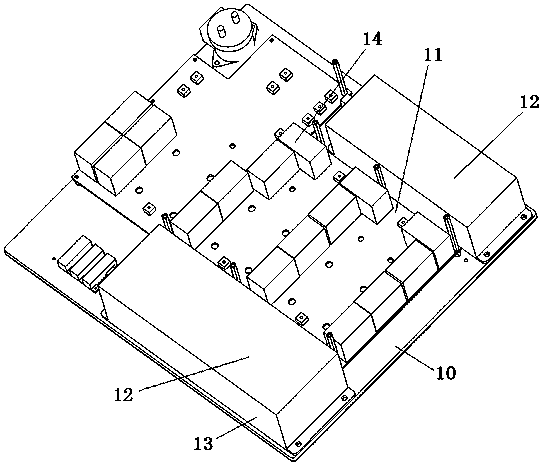
technical field [0001] The invention relates to a charging and discharging module and an inductance element thereof. Background technique [0002] In the prior art, if an electric vehicle wants to achieve fast charging, the output power of the power module must be increased, but the increase in output power will also cause serious heating of some components, and even stop working and explode. Traditional air-cooled heat dissipation can no longer meet the heat dissipation requirements of these high-power components, so water-cooled methods are mostly used in the prior art to dissipate heat from high-power components. [0003] Such as figure 1 As shown, it is an arrangement structure of a power module in the prior art. The power module includes a box body, and components and a cold plate 10 for cooling and dissipating the components are arranged inwardly. There are two types, which are the IGBT module and the inductance element 12 respectively. The box is also provided with...

Claims


Application Information

Patent Timeline
Patent Type & Authority Applications(China)
IPC IPC(8): H01F27/02H01F27/08H01F27/10B60L53/12
CPCB60L53/12H01F27/02H01F27/022H01F27/08H01F27/10Y02T10/70Y02T10/7072Y02T90/14
Inventor 杨浩宁程兴邦李林林贾甜张小广李谦
Owner XJ POWER CO LTD
Learn More