Spring welding structure of motor, winding structure and lens driving motor

A technology of welding structure and winding structure, which is applied in the field of motors, can solve the problems of affecting the axial movement state of the lens group, inconsistent number of winding coils, poor soldering and open circuit, etc., to improve the quality of welding connection, the number of winding coils is consistent, The effect of reasonable location layout

Pending Publication Date: 2020-03-31
NEW SHICOH MOTOR CO LTD
View PDF0 Cites 0 Cited by
  • Summary
  • Abstract
  • Description
  • Claims
  • Application Information

AI Technical Summary

Problems solved by technology

[0003] Among them, the prior art has the following defects: 1. The welding end of the spring piece is set to be F-shaped. Since the welding end of the spring piece needs to be welded and connected to the two ends of the coil, the F-shaped welding end is likely to cause solder offset and produce virtual welding. The problem of poor open circuit; 2. The two ends of the coil in the prior art, that is, the starting end and the ending end, are currently arranged in a diagonal or opposite side distribution mode, resulting in inconsistent numbers of coils on both sides, resulting in thrust (along the lens The axial thrust of the lens group) is unbalanced, which will affect the axial movement state of the lens group when shooting near and far

Method used


Image

  • Spring welding structure of motor, winding structure and lens driving motor
  • Spring welding structure of motor, winding structure and lens driving motor
  • Spring welding structure of motor, winding structure and lens driving motor

Examples


Embodiment 1

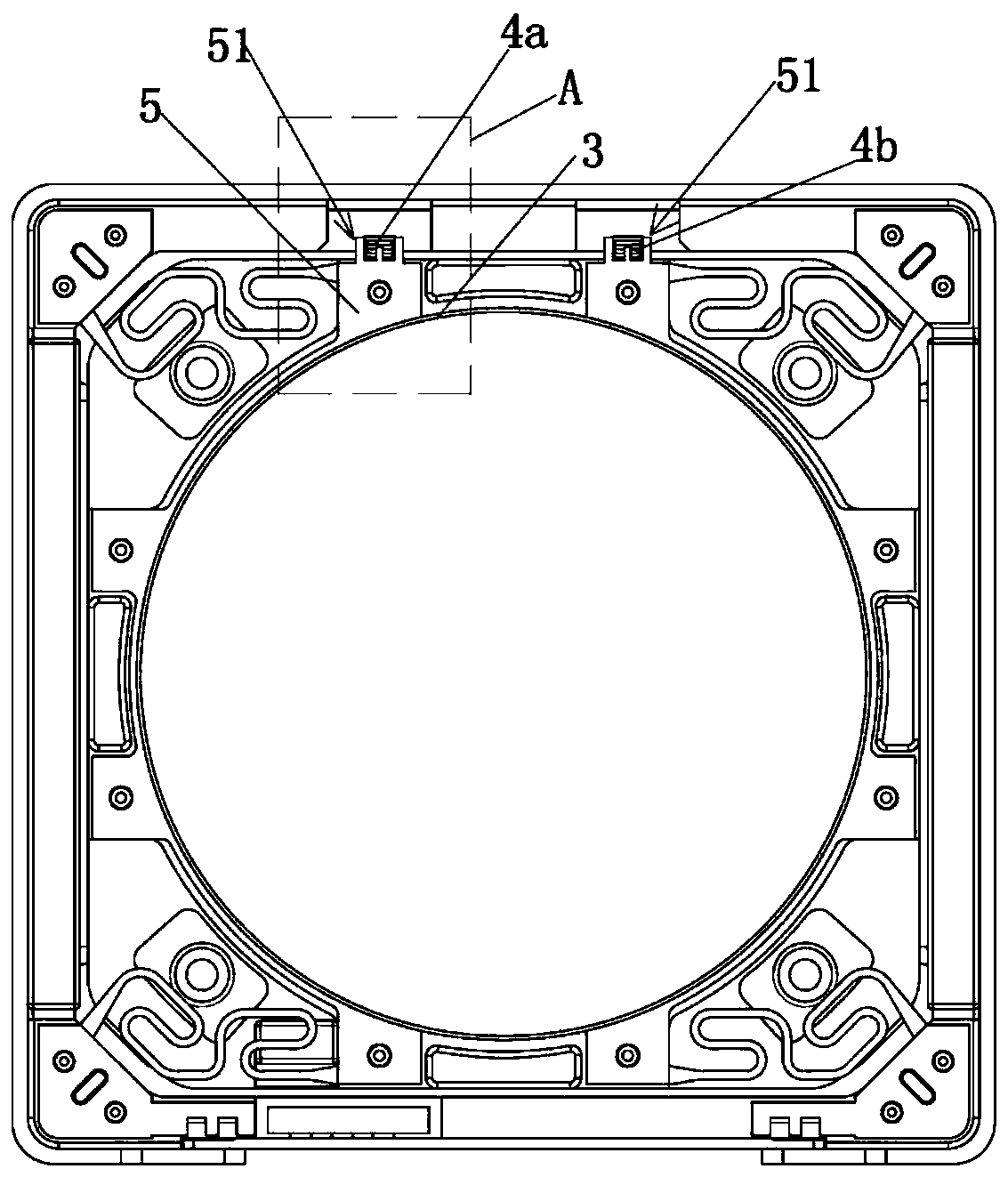
[0027] combine Figure 1-5 As shown, in order to ensure the firmness of the welding, the spring welding structure of the motor is set as follows: the spring sheet 5 has two welding ends 51 respectively welded to connect the first end 4a of the coil and the second end 4b of the coil, and the welding end 51 includes a pair of A connecting pin 51a for soldering connection, and a connecting reinforcing pin 51b between the two connecting pins 51a, a groove filled with solder is formed between the connecting pins 51a, so that the welding end 51 constitutes an "E" shaped structure, making the shape It is more beautiful; the above-mentioned connection and reinforcement foot 51b is in the middle position between the two connection feet 51a; the outer extension of the above-mentioned connection and reinforcement foot 51b is shorter than that of the connection foot 51a.

[0028] Since the connection reinforcement foot 51b is provided between the two connection feet 51a, the welding conta...

Embodiment 2

[0034] This embodiment can refer to Figure 4 A slight modification is made, and the spring welding structure of the motor is set as follows: the spring piece 5 has two welding ends 51 respectively welded to connect the first end 4a of the coil and the second end 4b of the coil, and the welding end 51 includes a pair of connections for welding connection Foot 51a, and two connection reinforcement feet 51b between the two connection feet 51a, a groove filled with solder is formed between the connection feet 51a, so that the welding end 51 forms an "E" shaped structure, making the shape more beautiful; the above connection The reinforcing leg 51b is located in the middle between the two connecting legs 51a; the outer extension of the connecting reinforcing leg 51b is shorter than the outer extension of the connecting leg 51a.

[0035] Since there are two connecting reinforcing feet 51b, the welding contact surface is further enlarged, so that the firmness of the welding is incre...


PUM


Abstract

The invention relates to the technical field of motors, in particular to a spring welding structure of a motor, a winding structure and a lens driving motor. The welding connection quality of the spring part and the coil is improved by improving the structures of the two welding ends of the spring part, due to the fact that the connecting reinforcing pins are arranged between the two connecting pins, the welding contact faces of the welding ends of the spring part and the first end and the second end of the coil are further increased, and the phenomenon of tin soldering deviation is avoided. The first coil end and the second coil end are arranged on the same side, namely, the starting end and the ending end of the coil are located on the same side, the number of coils wound on the two sides can be consistent, stress in a magnetic field is balanced, and therefore it is guaranteed that thrust in the axial direction of the lens set is in a balanced state.

Description

technical field [0001] The present invention relates to the technical field of motors, in particular to a lens driving motor used in a mobile terminal device. Background technique [0002] The main function of the voice coil motor (VCM) is to drive the lens to move for close-up and long-range shooting, and is widely used in mobile terminal devices such as mobile phones, notebook computers or tablet computers. A voice coil motor is a system consisting of a coil and a magnet. The electrified coil will be subjected to ampere force in the magnetic field, thereby driving the lens to move in the direction of the optical axis. [0003] Among them, the prior art has the following defects: 1. The welding end of the spring piece is set to be F-shaped. Since the welding end of the spring piece needs to be welded and connected to the two ends of the coil, the F-shaped welding end is likely to cause solder offset and produce virtual welding. The problem of poor open circuit; 2. The two...

Claims


Application Information

Patent Timeline
Patent Type & Authority Applications(China)
IPC IPC(8): H02K33/00H02K33/18H02K41/035H02K3/50G02B7/04G03B30/00
CPCH02K33/00H02K33/18H02K41/0356H02K3/50G02B7/04
Inventor 周良
Owner NEW SHICOH MOTOR CO LTD
Why Eureka
Try Eureka