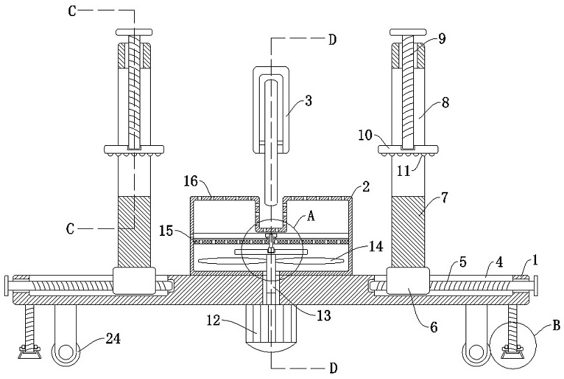
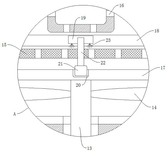
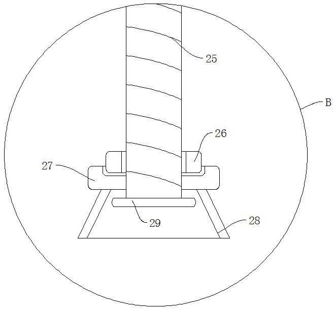
a metal cutting machine

A cutting machine and metal technology, which is applied in the direction of metal processing machinery parts, metal processing equipment, clamping, etc., can solve the problems of easy safety accidents, cutting errors of metal materials, and difficult ground cleaning, etc., and achieve the effect of increasing the convenience of use

Active Publication Date: 2021-01-05
LINYI LUYU MACHINERY
View PDF13 Cites 0 Cited by
  • Summary
  • Abstract
  • Description
  • Claims
  • Application Information

AI Technical Summary

Problems solved by technology

[0003] When the existing metal material is cut, the metal material is placed on the cutting frame by manual hand, and then it is cut, because in the process of cutting, the force of the cutting blade on the metal material is relatively large , so that it takes a lot of strength to hold the metal material manually, and it is more prone to safety accidents, and the existing cutting length of the metal material is measured in advance, and then it is placed on the cutting frame. Cutting, so that when the metal material is manually held for cutting, sometimes the position of the metal material will be shifted, causing errors in the cutting of the metal material. In addition, a large amount of powder will be produced when the cutting knife cuts the metal material. It will cause artificial adsorption of powder when cutting metal materials, which will cause harm to human health, and the powder after cutting will float and adhere to the ground, making it difficult to clean the ground

Method used


Image

  • a metal cutting machine
  • a metal cutting machine
  • a metal cutting machine

Examples


Embodiment Construction

[0027] The following will clearly and completely describe the technical solutions in the embodiments of the present invention with reference to the accompanying drawings in the embodiments of the present invention. Obviously, the described embodiments are only some, not all, embodiments of the present invention.

[0028] In describing the present invention, it should be understood that the terms "upper", "lower", "front", "rear", "left", "right", "top", "bottom", "inner", " The orientation or positional relationship indicated by "outside", etc. is based on the orientation or positional relationship shown in the drawings, and is only for the convenience of describing the present invention and simplifying the description, rather than indicating or implying that the referred device or element must have a specific orientation, so as to Specific orientation configurations and operations, therefore, are not to be construed as limitations on the invention.

[0029] refer to Figure ...


PUM


Abstract

The invention discloses a metal cutting machine, which comprises a base, wherein the upper end of the base is fixedly connected with a cutting box, the upper end of the base is fixedly connected witha cutting knife, grooves are symmetrically formed in the upper end of the base, the inner wall of each groove is rotatably connected with a first lead screw, each first lead screw is in threaded connection with a sliding block, and clamping devices for clamping a metal material are mounted on the sliding blocks. According to the invention, the metal material can be clamped and cut through the arrangement of vertical plates, threaded rods and arc-shaped clamping plates, and the occurrence of safety accidents caused by manually grasping and cutting the metal material is avoided. The metal cutting machine is provided with a rotating shaft, a negative pressure impeller and dust collection holes, the negative pressure impeller rotates to enable the cutting box to have negative pressure, and powder generated when the metal material is cut is absorbed to prevent the powder from scattering around to danger the body health of workers.

Description

technical field [0001] The invention relates to the technical field of cutting machines, in particular to a metal cutting machine. Background technique [0002] The metal cutting machine is a device used to cut metal materials. It can effectively cut metal materials of different shapes to obtain metal parts that meet the requirements. [0003] When the existing metal material is cut, the metal material is placed on the cutting frame by manual hand, and then it is cut, because in the process of cutting, the force of the cutting blade on the metal material is relatively large , so that it takes a lot of strength to hold the metal material manually, and it is more prone to safety accidents, and the existing cutting length of the metal material is measured in advance, and then it is placed on the cutting frame. Cutting, so that when the metal material is manually held for cutting, sometimes the position of the metal material will be shifted, causing errors in the cutting of the...

Claims


Application Information

Patent Timeline
Patent Type & Authority Patents(China)
IPC IPC(8): B23D79/00B23Q3/06B23Q11/00
CPCB23D79/00B23Q3/06B23Q11/0042B23Q11/0046
Inventor 张洪梅
Owner LINYI LUYU MACHINERY
Why Eureka
Try Eureka