Solid shaft chamfering device

A technology of chamfering device and solid shaft, which is applied in the direction of feeding device, metal processing machinery parts, metal processing, etc., can solve the problems of high manufacturing cost, low work efficiency, heavy workload of workers, etc., achieve high work efficiency and reduce work Quantity, good safety effect

Active Publication Date: 2020-04-03
JIANGXI EQUIP INDAL GROUP GREAT INSURANCENT
View PDF12 Cites 10 Cited by
  • Summary
  • Abstract
  • Description
  • Claims
  • Application Information

AI Technical Summary

Problems solved by technology

[0004] The object of the present invention is to provide a solid shaft chamfering device to solve the above-mentioned background technology. The current chamfering of solid shafts generally requires workers to install the solid shaft on a lathe, and then operate the lathe to perform chamfering. Clamp the solid shaft, and then perform chamfering on the manual lathe, which has the problems of low work efficiency, heavy workload and high manufacturing cost.

Method used


Image

  • Solid shaft chamfering device
  • Solid shaft chamfering device
  • Solid shaft chamfering device

Examples


Embodiment Construction

[0022] The following will clearly and completely describe the technical solutions in the embodiments of the present invention with reference to the accompanying drawings in the embodiments of the present invention. Obviously, the described embodiments are only some, not all, embodiments of the present invention. The specific embodiments described here are only used to explain the present invention, not to limit the present invention. Based on the embodiments of the present invention, all other embodiments obtained by persons of ordinary skill in the art without making creative efforts belong to the protection scope of the present invention.

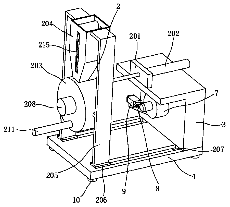
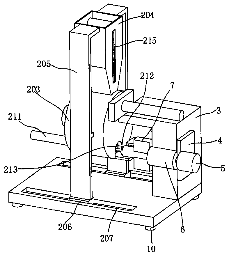
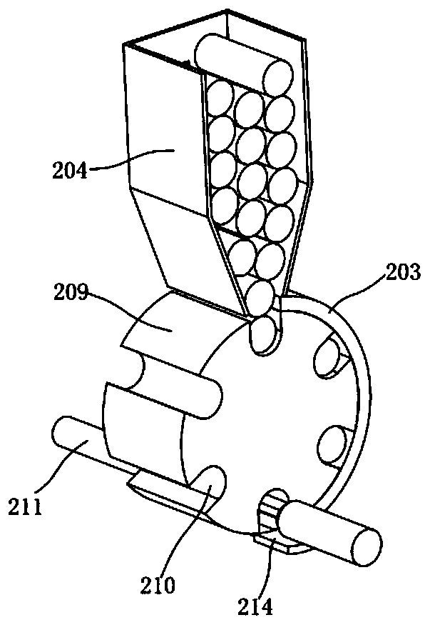
[0023] Such as figure 1 and figure 2 As shown, the present invention provides a solid shaft chamfering device, including a mounting block 1, in order to improve the stability and firmness of the whole device, bases 10 are fixed at the bottom four corners of the mounting block 1, and the mounting block 1 One side is provided with automa...


PUM


Abstract

The invention discloses a solid shaft chamfering device. The solid shaft chamfering device comprises an installation block, one side of the installation block is provided with an automatic feeding device, the end, away from the automatic feeding device, of the installation block is fixedly provided with a supporting block, a first installation plate is fixedly arranged in the middle of the rear side of the supporting block, and a first servo motor is fixedly arranged on the first installation plate. The end of an output shaft of the first servo motor is fixedly provided with a rotary shaft, the rotary shaft is rotationally connected with a supporting block through a bearing, a hydraulic chuck is fixedly arranged on the end portion of the end, away from the first servo motor, of the rotaryshaft, the hydraulic chuck is located at the front end of the outer side of the supporting block, an installation rack is arranged on one side of the hydraulic chuck, the installation rack is fixed tothe front side of the supporting block, and the installation rack is provided with a chambering mechanism. Automatic feeding and chamfering are conducted without manual operation, the working efficiency is high, and the labor cost is saved.

Description

technical field [0001] The invention belongs to the technical field of solid shaft chamfering devices, in particular to a solid shaft chamfering device. Background technique [0002] The shaft is a cylindrical object that goes through the middle of the bearing or the middle of the wheel or the middle of the gear, but a small part is also square. A shaft is a mechanical part that supports and revolves with a rotating part to transmit motion, torque or bending moment. Generally, it is in the shape of a metal round rod, and each segment can have different diameters. The parts that make rotary motion in the machine are mounted on the shaft. Common shafts can be divided into crankshafts, straight shafts, flexible shafts, solid shafts, hollow shafts, rigid shafts, and flexible shafts according to the structural shape of the shaft. [0003] The solid shaft is used in many machines, and it is generally necessary to adjust the parts on the solid shaft. In order to facilitate the s...

Claims


Application Information

Patent Timeline
Patent Type & Authority Applications(China)
IPC IPC(8): B23D79/00B23Q7/02B23Q7/10B23Q5/40B23Q5/36
CPCB23D79/00B23Q5/36B23Q5/40B23Q7/02B23Q7/10
Inventor 徐迪
Owner JIANGXI EQUIP INDAL GROUP GREAT INSURANCENT
Why Eureka
Try Eureka