Tin soldering device for I-shaped inductor processing

An I-shaped inductor and soldering technology, applied in auxiliary devices, metal processing, metal processing equipment, etc., can solve the problems of weak welding position, reduced inductance quality, poor solder joint forming quality, etc., to improve processing quality and production. Efficiency, improve stability and reliability, and improve the effect of product qualification rate

Inactive Publication Date: 2020-04-03
湖南碧建精密机械有限公司
View PDF0 Cites 1 Cited by
  • Summary
  • Abstract
  • Description
  • Claims
  • Application Information

AI Technical Summary

Problems solved by technology

[0003] At present, the tin immersion process of I-shaped inductance processing is mainly performed by manual operations alone, which is labor-intensive, low in efficiency, and the quality of tin immersion is difficult to guarantee. Different employees are prone to false soldering when immersing tin, and the welding position is not firm. , the pins are easy to fall off, the quality of the solder joints is poor, the position of the solder joints is uneven and the shape is not beautiful, and some existing automatic welding machines have the following technical problems: 1. During the process of picking up the I-shaped inductor, If the clamping force is too large, it is easy to damage the enameled wire wrapped with the I-shaped inductor coil, causing the coil to be pinched or misplaced, resulting in a decrease in the quality of the inductor and an increase in the rate of unqualified products; 2. I-shaped inductors It is easy to drop when loading materials, causing the inductor to fall into the flux tank or tin melting furnace, which not only pollutes and destroys the flux or tin liquid, but also leads to increased production costs and mass production quality problems; 3. With During the tin immersion process, the flux liquid level in the flux tank and the tin liquid level in the tin melting furnace begin to drop, resulting in insufficient tin liquid or flux during soldering, which makes the soldering of the inductance pins weak

Method used


Image

  • Tin soldering device for I-shaped inductor processing
  • Tin soldering device for I-shaped inductor processing
  • Tin soldering device for I-shaped inductor processing

Examples


Embodiment Construction

[0025] In order to enable those skilled in the art to better understand the technical solution of the present invention, the present invention will be described in detail below in conjunction with the accompanying drawings. The description in this part is only exemplary and explanatory, and should not have any limiting effect on the protection scope of the present invention. .

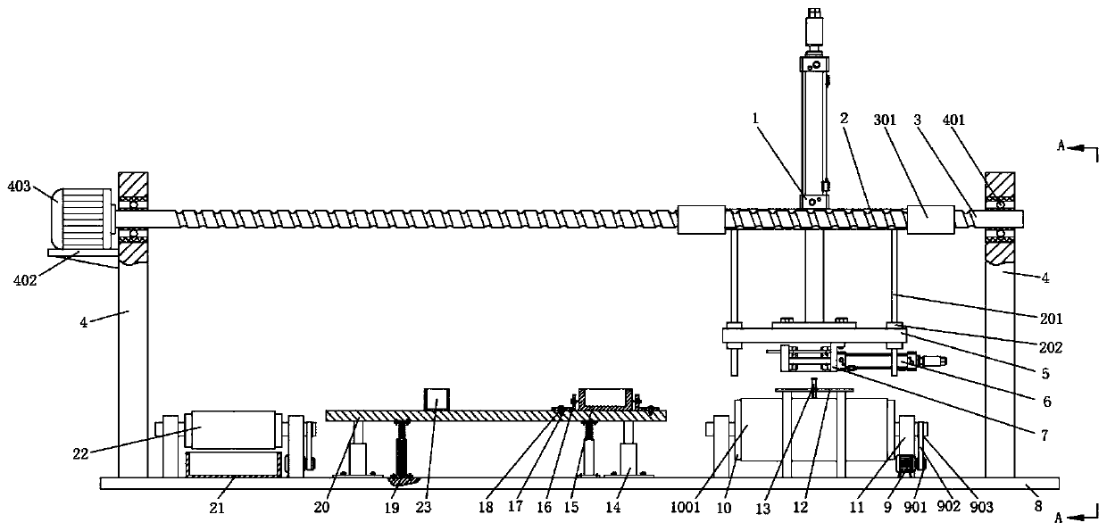
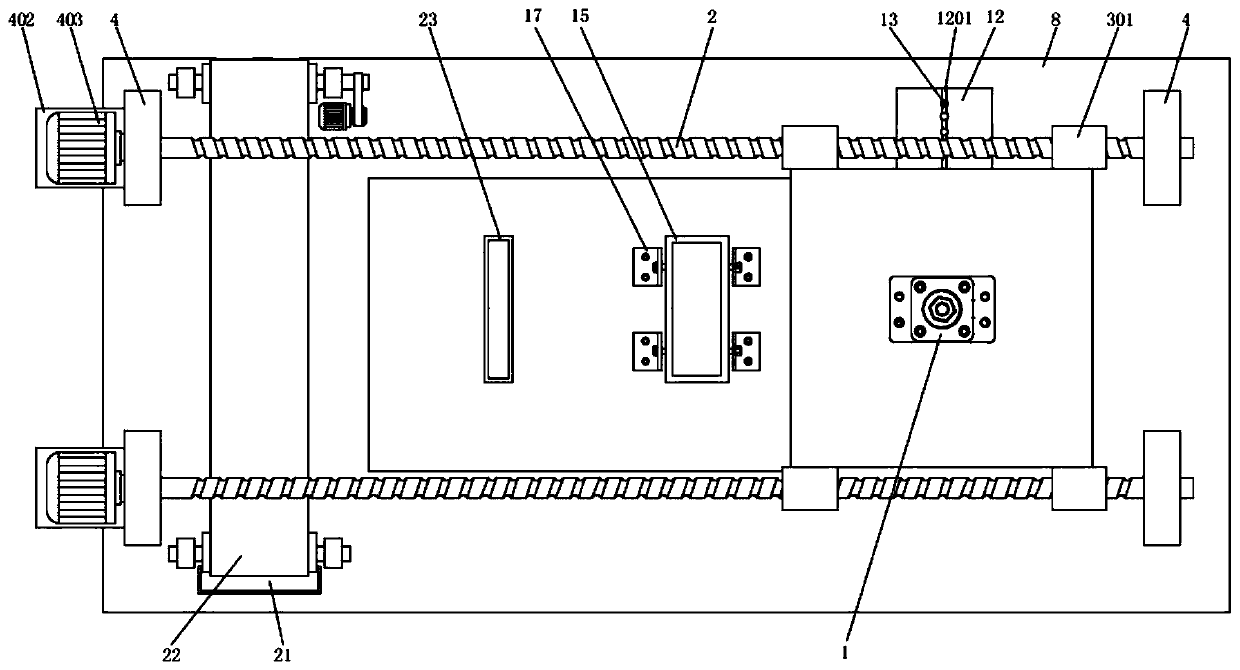
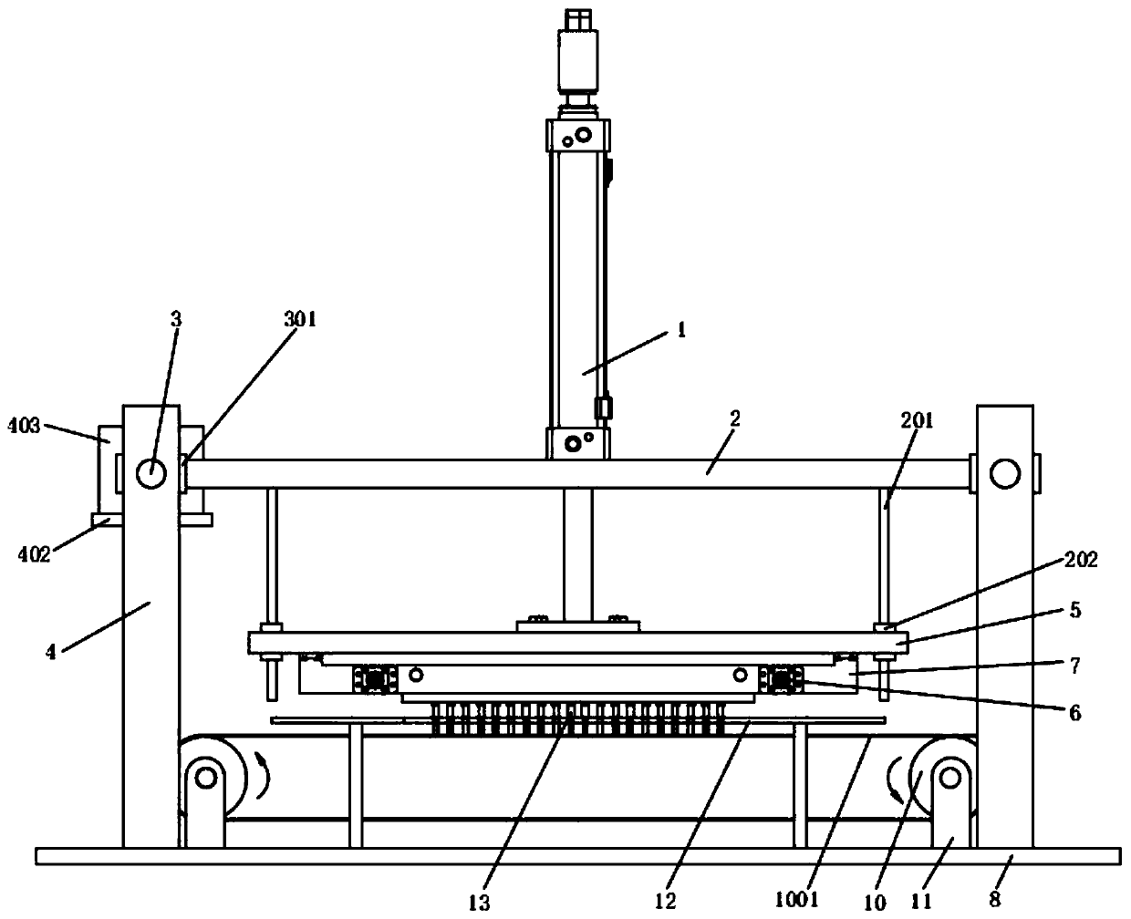
[0026] Such as Figure 1-Figure 6 Shown, the specific structure of the present invention is: it comprises base plate 8, and base plate 8 tops are provided with four brackets 4 at fixed intervals, and screw mandrel 3 is set horizontally and laterally in brackets 4, and screw mandrel nut 301 is arranged at spacing on screw mandrel 3, and screw mandrel 3 The side end of the rod nut 301 is fixedly provided with a supporting platform 2, and the middle part of the upper surface of the supporting platform 2 is provided with a lifting cylinder 1. The material mechanism 7, below the material clamping mechanism...


PUM


Abstract

The invention discloses a tin soldering device for I-shaped inductor processing. The device comprises a baseplate, wherein four supports are disposed at a fixed interval on the top of the baseplate; alead screw is disposed horizontally and horizontally disposed inside the supports in a rotatable manner; lead screw nuts are disposed at an interval on the lead screw; a supporting table is fixedly disposed on a side end of the lead screw nuts; a lifting air cylinder is disposed at the center of the upper surface of the supporting table; a telescopic end of the lifting air cylinder passes throughthe supporting table downwards and is fixedly connected to a lifting table; and a clamping mechanism is disposed on the lower surface of the lifting table. The device disclosed by the invention has the beneficial effects that tin soaking can be conducted on multiple I-shaped inductors at a time; during material fetching, clamping damage to the I-shaped inductors can be effectively prevented; processing quality and production efficiency are increased; and insufficient soldering caused by decrease of a soldering flux or a tin liquid can be prevented.

Description

technical field [0001] The invention relates to the technical field of induction processing, in particular to a soldering device for H-shaped induction processing. Background technique [0002] At present, in various circuit systems, inductance coils play an extremely important role and have been widely used. During the processing of I-shaped inductance, it is necessary to carry out the processing steps of feeding, winding, presser foot, tin dipping, and casing. I-shaped inductors are dipped in tin by first dipping flux at the connection of the pins, and then dipping in tin liquid, so that the pins of the I-shaped inductors are welded and fixed. [0003] At present, the tin immersion process of I-shaped inductance processing is mainly performed by manual operations alone, which is labor-intensive, low in efficiency, and the quality of tin immersion is difficult to guarantee. Different employees are prone to false soldering when immersing tin, and the welding position is not ...

Claims


Application Information

Patent Timeline
Patent Type & Authority Applications(China)
IPC IPC(8): B23K1/08B23K3/08B23K101/36
CPCB23K1/08B23K3/08B23K3/087B23K2101/36
Inventor 肖杰杨小英李海剑杨顺
Owner 湖南碧建精密机械有限公司
Why Eureka
Try Eureka