Eureka AIR delivers breakthrough ideas for toughest innovation challenges, trusted by R&D personnel around the world.

Simulated Christmas tree leaf cutting and arranging device

A technology for arranging devices and Christmas trees, which is applied in metal processing and other directions, can solve the problems of high labor intensity, low production efficiency, short size of leaves, etc., and achieve the effects of convenient and neat arrangement, improving production efficiency and reducing labor costs.

Active Publication Date: 2020-04-03
赣州东峰自动化设备有限公司
View PDF7 Cites 2 Cited by
  • Summary
  • Abstract
  • Description
  • Claims
  • Application Information

AI Technical Summary

Problems solved by technology

[0002] During Christmas and other times, simulated Christmas trees are often used to decorate. The simulated Christmas tree is usually assembled from multiple simulated Christmas tree branches. Umbrella-shaped, that is, the length of the Christmas tree branches decreases from bottom to top, resulting in the formation of Christmas tree leaves requires molding molds of different specifications corresponding to different sizes of Christmas tree leaves, and the formed leaves cannot be neatly arranged and packaged due to their short size. It can only be used by dumping the formed leaves into the packing box and then packing them to the artificial Christmas tree manufacturer. When the Christmas tree manufacturer uses them, because the leaves of the Christmas tree are interlaced and stacked together, a lot of manpower is required to arrange the leaves neatly on the assembly line. Supply to manipulator, labor intensity is high, production cost is high, and production efficiency is very low

Method used


Image

  • Simulated Christmas tree leaf cutting and arranging device
  • Simulated Christmas tree leaf cutting and arranging device
  • Simulated Christmas tree leaf cutting and arranging device

Examples


Embodiment Construction

[0025] Below in conjunction with accompanying drawing, the embodiment of the present invention is described in detail:

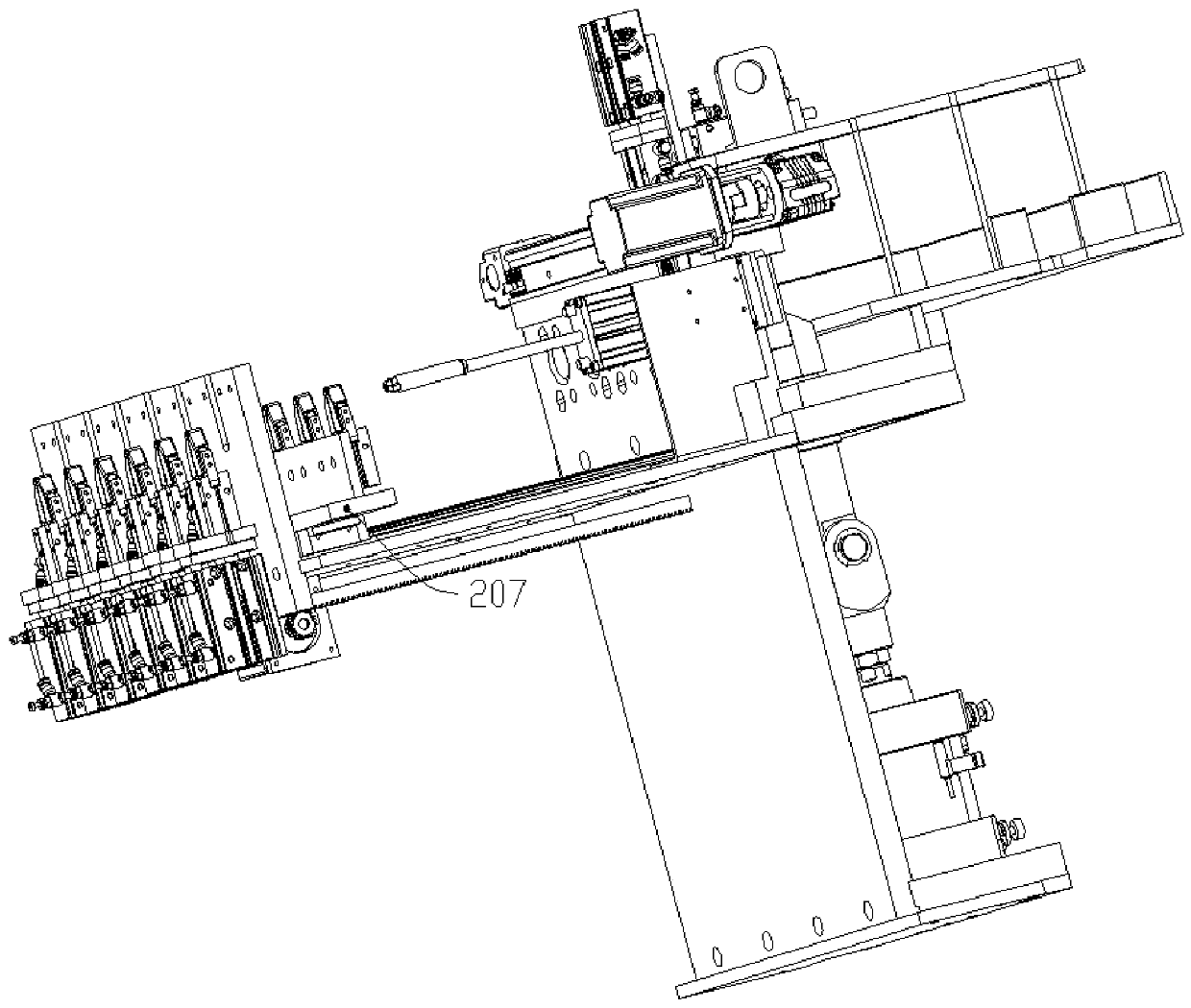
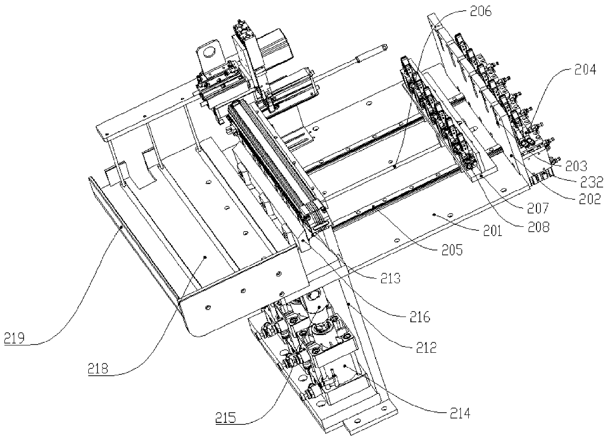
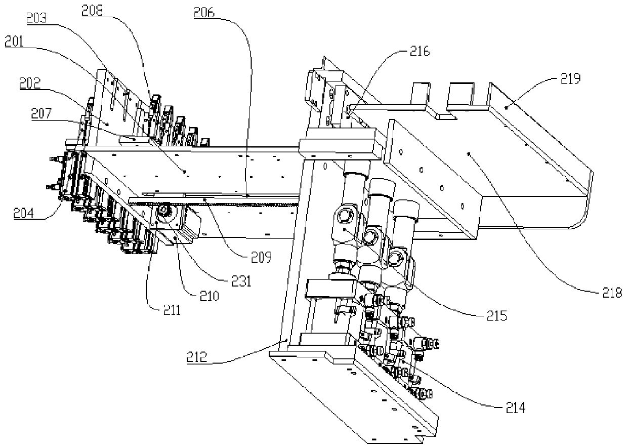
[0026] Such as Figure 1 to Figure 6 As shown, the present invention discloses a device for cutting and arranging simulated Christmas tree leaves. The plate 202 is evenly fixed with a plurality of leaf feeding grooves 203 that run through the leaf feeding support plate 202, and leaf fixing mechanisms are fixed on the right end surface of the leaf feeding supporting plate 202 corresponding to the leaf feeding grooves 203. The leaf fixing mechanisms include vertically fixed The fixed cylinder 232 on the leaf support plate 202 is fixed with the leaf clamp finger cylinder 204 above the fixed cylinder 232 through the piston rod of the fixed cylinder 232, and there are many vertical leaf support plates 202 fixed on the leaf base plate 201. The leaf guide rail 205 is fixed on the leaf feed guide rail 205 through the leaf feed slider 230 and the leaf feed guide rail ...


PUM


Abstract

The invention relates to the technical field of simulated Christmas tree equipment, in particular to a simulated Christmas tree leaf cutting and arranging device which comprises a leaf feeding substrate fixed on a rack. A leaf feeding support plate is fixed on the right side of the leaf feeding substrate, a plurality of leaf feeding grooves penetrating through the leaf feeding support plate are uniformly fixed on the leaf feeding support plate, and leaf fixing mechanisms are fixed at positions, corresponding to the leaf feeding grooves, on the right end face of the leaf feeding support plate.Each leaf fixing mechanism comprises a fixing air cylinder vertically fixed on the leaf feeding support plate, wherein a leaf feeding clamping finger air cylinder is fixed above the fixing air cylinder through a piston rod of the fixing air cylinder, a plurality of leaf feeding guide rails perpendicularly fixed by the leaf feeding support plate are fixed on the leaf feeding substrate, and leaf feeding sliding plates which pass through leaf feeding sliding blocks and the leaf feeding guide rails and are in sliding connection with the leaf feeding guide rails are fixed on the leaf feeding guiderails. The device can simultaneously cut a plurality of long Christmas tree leaves into short Christmas tree leaves.

Description

【Technical field】 [0001] The invention relates to the technical field of simulated Christmas tree equipment, in particular to a device for cutting and arranging simulated Christmas tree leaves. 【Background technique】 [0002] During Christmas and other times, simulated Christmas trees are often used to decorate. The simulated Christmas tree is usually assembled from multiple simulated Christmas tree branches. Umbrella-shaped, that is, the length of the Christmas tree branches decreases from bottom to top, resulting in the formation of Christmas tree leaves requires molding molds of different specifications corresponding to different sizes of Christmas tree leaves, and the formed leaves cannot be neatly arranged and packaged due to their short size. It can only be used by dumping the formed leaves into the packing box and then packing them to the artificial Christmas tree manufacturer. When the Christmas tree manufacturer uses them, because the leaves of the Christmas tree ar...

Claims


Application Information

Patent Timeline
Patent Type & Authority Applications(China)
IPC IPC(8): B26D1/06B26D7/02B26D7/06B26D7/32B26D7/18B26D7/28
CPCB26D1/06B26D7/02B26D7/06B26D7/18B26D7/28B26D7/32
Inventor 廖胜明
Owner 赣州东峰自动化设备有限公司
Why Eureka
Eureka Blog
Learn More