Application method of lifting safe guardrail device

A safety guardrail, lift-type technology, applied in the direction of fences, construction materials, bridge parts, etc., can solve the problems of increased high-altitude edge safety risks, lack of protective measures, hindering the normal use of mechanical equipment, etc., to avoid edge operations. Status, safe return to normal height, and the effect of reducing safety risks

Active Publication Date: 2020-04-03
SHANGHAI NO 4 CONSTR
View PDF7 Cites 0 Cited by
  • Summary
  • Abstract
  • Description
  • Claims
  • Application Information

AI Technical Summary

Problems solved by technology

[0003] However, when there are soil fetching and digging operations on the side of the foundation pit or on the trestle bridge, the height of the fixed-height railings will hinder the normal use of

Method used


Image

  • Application method of lifting safe guardrail device
  • Application method of lifting safe guardrail device
  • Application method of lifting safe guardrail device

Examples


Embodiment 1

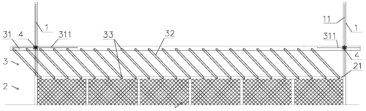
[0037] see Figure 1 to Figure 5 , the invention discloses a method for using a liftable safety guardrail device, the liftable safety guardrail device comprising: a guardrail arranged between adjacent fixed columns 1 and a guardrail height locking mechanism 4, the guardrail It includes a fixed guardrail 2 and a movable guardrail 3, the movable guardrail 3 is arranged above the fixed guardrail 2, the height of the movable guardrail 3 can be adjusted, and the guardrail height locking mechanism 4 can lock the movable guardrail 3 to the fixed column 1, so that the movable guardrail 3 maintains the required height position, the method comprises the following steps:

[0038] The first step is to install the liftable safety guardrail device on the construction site;

[0039] The second step is to loosen the guardrail height locking mechanism 4, and adjust the height of the movable guardrail 3 as required;

[0040] The third step is to lock the guardrail height locking mechanism 4, an...

Embodiment 2

[0054] see Figure 6 to Figure 7 , the difference between this embodiment and Embodiment 1 is:

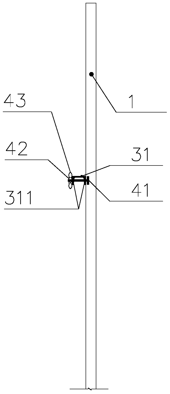
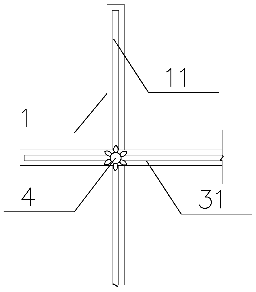
[0055] The height locking mechanism of the guardrail includes a screw mandrel 44, a nut 42 and an anti-rotation block 45. A vertical chute 11 is provided on the fixed column, and a horizontal chute 311 is provided on the upper rail 31 of the movable guardrail. The screw mandrel 44 One end of the screw rod 44 is fixedly connected with the anti-rotation block 45, and the other end of the screw rod 44 passes through the vertical chute 11 of the fixed column 1 and the horizontal chute 311 of the upper file 31 of the movable guardrail, and then is fixed by the nut 42. , the anti-rotation block 45 is located inside the fixed column 1 , and the fixed column 1 can limit the rotation of the anti-rotation block 45 around the axis of the screw rod 44 inside the fixed column 1 .

[0056] The anti-rotation block, on the one hand, can be used as a limiting device to prevent the screw rod 44 fro...

Embodiment 3

[0061] see Figure 10 , the difference between this embodiment and Embodiment 1 is:

[0062] Described movable guardrail 3 comprises movable guardrail upper gear 31, middle cross bar 34 and several connecting rods 32, and described middle cross bar 34 is positioned between described movable guardrail upper gear 31 and fixed guardrail 2, and described movable guardrail upper gear 31 Between the middle cross bar 34 and between the fixed guardrail 2 and the middle cross bar 34, a number of parallel connecting rods 32 are respectively arranged in a hinged manner, and the upper and lower adjacent connecting rods 32 are hinged at the same place of the middle cross bar 34. Adjacent connecting rods 32 form an isosceles triangle with the plumb line or are collinear with the plumb line.

[0063] In this embodiment, the connecting rod 32 between the upper rail 31 of the movable guardrail and the fixed guardrail 2 is divided by the middle cross bar 34, so that the connecting rod 32 is si...


PUM


Abstract

The invention provides an application method of a lifting safe guardrail device. A protection guardrail arranged between adjacent fixed stand columns and guardrail height locking mechanisms are adopted. The protection guardrail comprises a fixed guardrail and a moving guardrail. The moving guardrail is arranged above the fixed guardrail. The height of the moving guardrail can be adjusted accordingto needs. When soil taking, soil excavation and other work are carried out beside foundation pits and on bridges, the operation of demounting a mounted guardrail device in order to provide operationspace for normal use of mechanical equipment is not needed, only the moving guardrail needs to be lowered to the needed height, and the moving guardrail can be locked on the fixed stand columns through the guardrail height locking mechanisms. In the work process of the mechanical equipment, the moving guardrail with the height reduced still can keep the guardrail function. After work of the mechanical equipment is finished, the normal height of the moving guardrail can be restored rapidly, conveniently and safely, and therefore the guardrail-free limb work state is effectively avoided, and thesafety risk of limb work is reduced.

Description

technical field [0001] The invention relates to the field of safety protection, in particular to a method for using a liftable safety guardrail device. Background technique [0002] The protective railings on the edge of the foundation pit at the construction site are generally erected with steel pipe fasteners, and those with higher civilized construction standards adopt stereotyped products. The height of the railings is about 1.2m-1.8m. use. [0003] However, when there are soil fetching and digging operations on the side of the foundation pit or on the trestle bridge, the height of the fixed-height railings will hinder the normal use of mechanical equipment, often resulting in the removal of the installed railings, resulting in the lack of protective measures for this part , The risk of high-altitude border security has greatly increased. According to incomplete statistics, safety accidents caused by high-altitude edge accounted for more than 50% of the national constr...

Claims


Application Information

Patent Timeline
IPC IPC(8): E04H17/14E04G21/32E01D19/10
CPCE01D19/103E04G21/3204E04H17/14
Inventor 马晓辉匙文成陈一琼王一凡俞文俊蔡杰殷凯
Owner SHANGHAI NO 4 CONSTR
Why Eureka
Try Eureka