Supercharge Your Innovation With Domain-Expert AI Agents!

Thrust washer

A thrust washer and inner ring technology, which is applied in the field of industrial parts, can solve the problems of easy disassembly, looseness, inconvenient installation, etc., and achieve the effect of avoiding relative distance, preventing falling apart, and improving the stability effect

Active Publication Date: 2020-04-03
临沂金盛机械配套有限公司
View PDF10 Cites 0 Cited by
  • Summary
  • Abstract
  • Description
  • Claims
  • Application Information

AI Technical Summary

Problems solved by technology

[0003] Since the thrust bearing is composed of two thrust washers or more thrust washers and a number of rolling elements, the shaft and seat of the thrust washers are parallel and have no stable connection with each other. During the transportation of freight trains, when encountering a sharp turn on the track, because the body is long, the body is subjected to the centripetal force of the inner curved side of the body during the sharp turn, which makes the body tilt to a certain extent during operation. Due to the effect of centripetal force, there is also a tendency of inclination. In the winding mountain area, the thrust bearing is often subjected to reciprocating centripetal effect, so that the shaft plate and gasket of the thrust bearing often reciprocate and shift, which is easy to cause shaking and loosening. The existing There is no direct and stable connection relationship between the shaft piece and the seat piece during the specific use process, so that when the thrust bearing is used vertically, the thrust washer is not easy to install when installed, and it is easy to fall off when disassembled. The connection method hinders the overall rotation of the thrust bearing

Method used


Image

  • Thrust washer
  • Thrust washer
  • Thrust washer

Examples


Embodiment Construction

[0024] In order to make the technical means, creative features, goals and effects achieved by the present invention easy to understand, the present invention will be further described below in conjunction with specific embodiments.

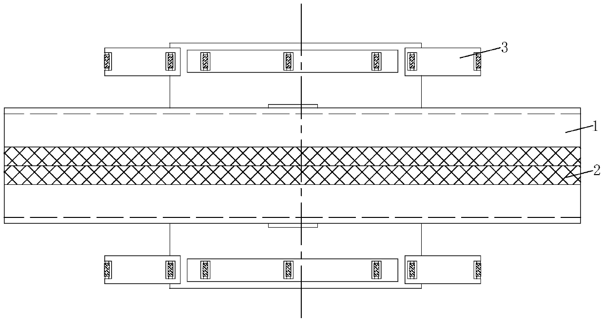
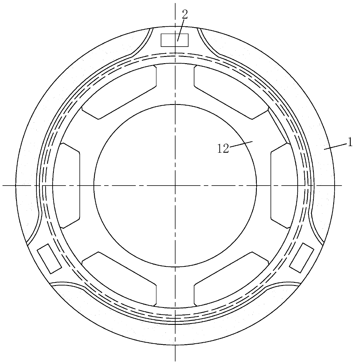
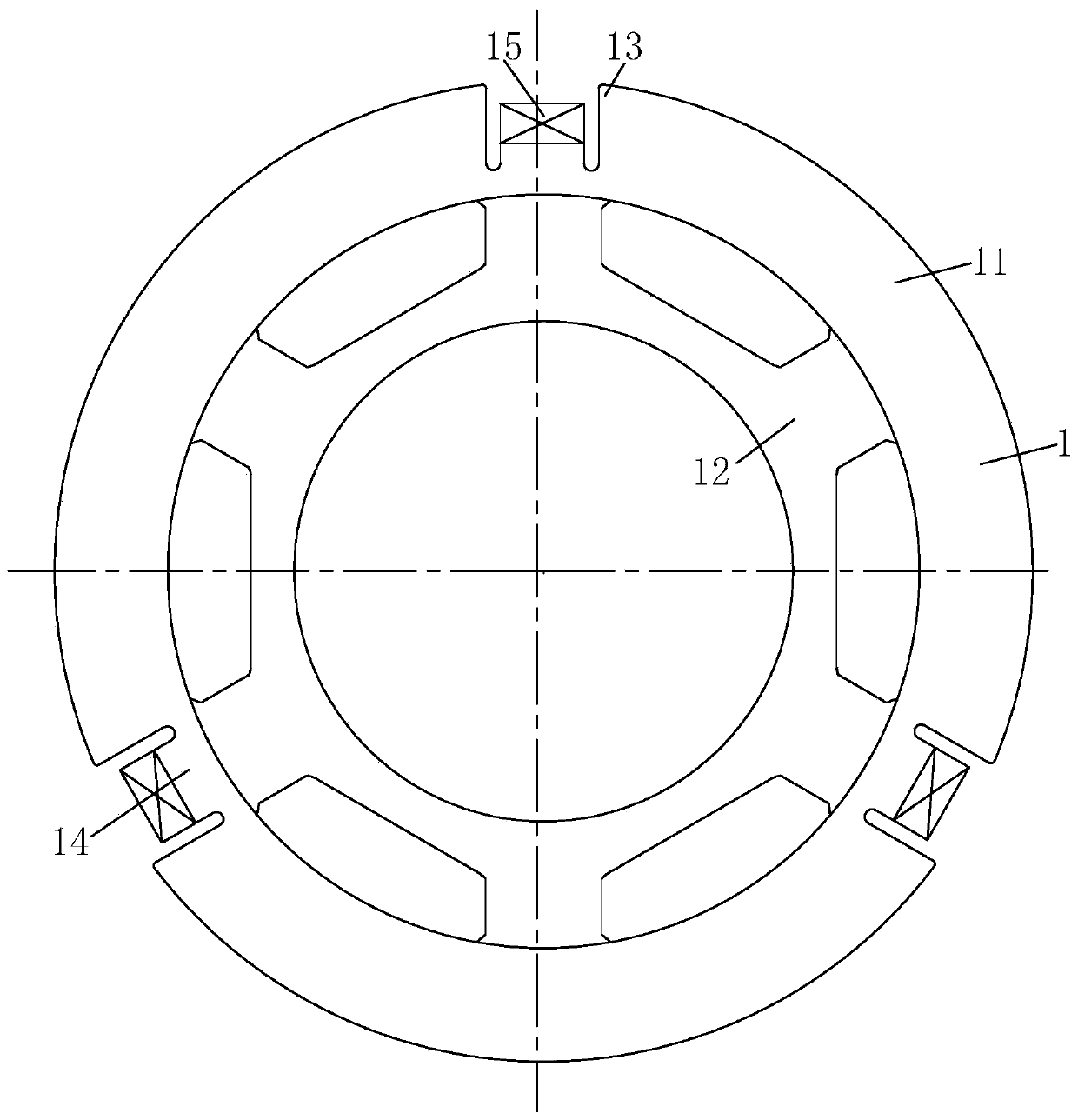
[0025] like Figure 1-Figure 7 As shown, a thrust washer according to the present invention includes a shaft plate subassembly 1, a shaft plate female assembly 2 and a connecting assembly 3, the opposite sides of the shaft plate female assembly 2 are fixedly connected, and the shaft plate female assembly 2 The opposite side of the shaft piece wood assembly is clamped, the shaft piece subassembly 1 includes a first shaft piece 11, the shaft piece mother assembly 2 includes a second shaft piece 21, and the inner ring of the first shaft piece 11 is fixed Connected with an inner mounting ring 12, the inner ring of the inner mounting ring 12 is fixedly connected with a connection assembly 3, and the connection assembly 3 includes a connection block 31,...


PUM


Abstract

The invention relates to the field of industrial parts, in particular to a thrust washer which comprises a shaft piece sub-assembly, a shaft piece mother assembly and a connecting assembly. The opposite sides of the shaft piece mother assembly are fixedly connected, the opposite sides of the shaft piece mother assembly are connected with a shaft piece wood assembly in a clamped mode, the shaft piece sub-assembly comprises a first shaft piece, and the shaft piece mother assembly comprises a second shaft piece. Through a connection assembly, a shaft plate of a thrust backing plate is conveniently and stably connected with a base plate, thereby preventing the thrust bearing from being subjected to a reciprocating centripetal effect in the transporting process, and preventing easy wobble and loosening due to the fact that the shaft sheet and the gasket of the thrust bearing always deviate in a reciprocating manner, improving stability of the thrust bearing and preventing the thrust bearingfrom loosing and shedding; and through arrangement of a sliding assembly, a roller shaft of the sliding assembly is in lap joint with an inner ring of the base plate of the thrust bearing, and matched transverse tooth grooves are formed in the roller shaft and the inner ring of the base plate while smooth rotation of the base plate is kept, so that relative separation of the shaft plate and the base plate is avoided, and mounting and dismounting are facilitated.

Description

technical field [0001] The invention relates to the field of industrial parts, in particular to a thrust washer. Background technique [0002] Thrust bearings are generally composed of two thrust washers or more thrust washers and a number of rolling elements. Generally, thrust washers are divided into shaft pieces and seat pieces. The most common types of rolling elements are generally made of iron or copper. The quality cage is combined into a whole. The most common type of bearing is steel ball thrust bearing. Thrust bearings are designed and used to bear axial loads. They are also called axial bearings. These bearings include thrust ball bearings, thrust Cylindrical roller bearings, thrust needle roller bearings, thrust tapered roller bearings and thrust self-aligning roller bearings, thrust washers are annular plates or two semi-annular plates usually used with radial sliding bearings to withstand axial loads , The thrust washer is a standard part used in conjunction w...

Claims


Application Information

Patent Timeline
IPC IPC(8): F16C19/12F16C33/30F16C35/07
CPCF16C19/12F16C33/30F16C35/07
Inventor 牧尚祥董和
Owner 临沂金盛机械配套有限公司
Features
  • R&D
  • Intellectual Property
  • Life Sciences
  • Materials
  • Tech Scout
  • Unparalleled Data Quality
  • Higher Quality Content
  • 60% Fewer Hallucinations
Learn More