Wind pressure control method and device, gas water heater and storage medium

A wind pressure control and wind pressure technology, which is applied in the fields of gas water heaters, storage media, devices, and wind pressure control methods, can solve the problems of wind pressure response control delay, low accuracy, large error, etc., and achieves timely control response and improved Effects of Wind Pressure Compensation Accuracy

Inactive Publication Date: 2020-04-03
CHONGQING HAIER WATER HEATER
View PDF5 Cites 6 Cited by
  • Summary
  • Abstract
  • Description
  • Claims
  • Application Information

AI Technical Summary

Problems solved by technology

Due to the lengthy response transmission link in the whole adjustment process, and each link takes a certain amount of time, it will cause hysteresis in the wind pressure response control process
In addition, the existing technology judges whether the air volume is sufficient by calculating elements such as fan power or current, and there are differences between the two to a certain extent, coupled with the influence of calculation and calibration errors and hysteresis responses in various links in the middle, resulting in errors in the existing technology bigger, less precise
[0005] In summary, the wind pressure control method in the prior art has problems such as control response hysteresis and low accuracy.

Method used


Image

  • Wind pressure control method and device, gas water heater and storage medium
  • Wind pressure control method and device, gas water heater and storage medium
  • Wind pressure control method and device, gas water heater and storage medium

Examples


Embodiment 1

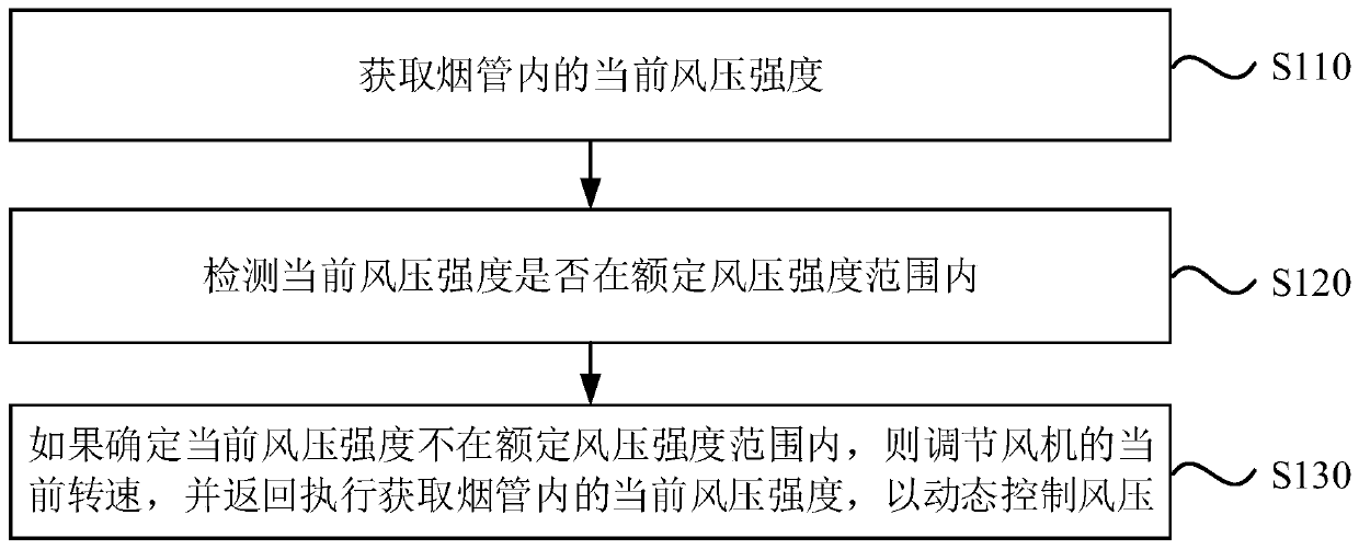
[0028] figure 1 It is a schematic flowchart of a wind pressure control method provided in Embodiment 1 of the present invention. This method is applicable to the situation of controlling the wind pressure in the flue pipe of a gas water heater, and the method can be implemented by a wind pressure control device, which can be composed of hardware and / or software, and can generally be integrated in a gas water heater and all In equipment that uses fan blast combustion heating function. Specifically include the following:

[0029] S110. Obtain the current wind pressure intensity in the smoke pipe.

[0030] Along with the widespread use of gas water heaters, gas water heaters have become one of the necessary household appliances for every household. However, in the process of using a gas water heater, when the windy weather or the exhaust port of the flue is blocked, it often occurs that it is difficult to ignite, ignite and deflagrate during the ignition process, or incomplete...

Embodiment 2

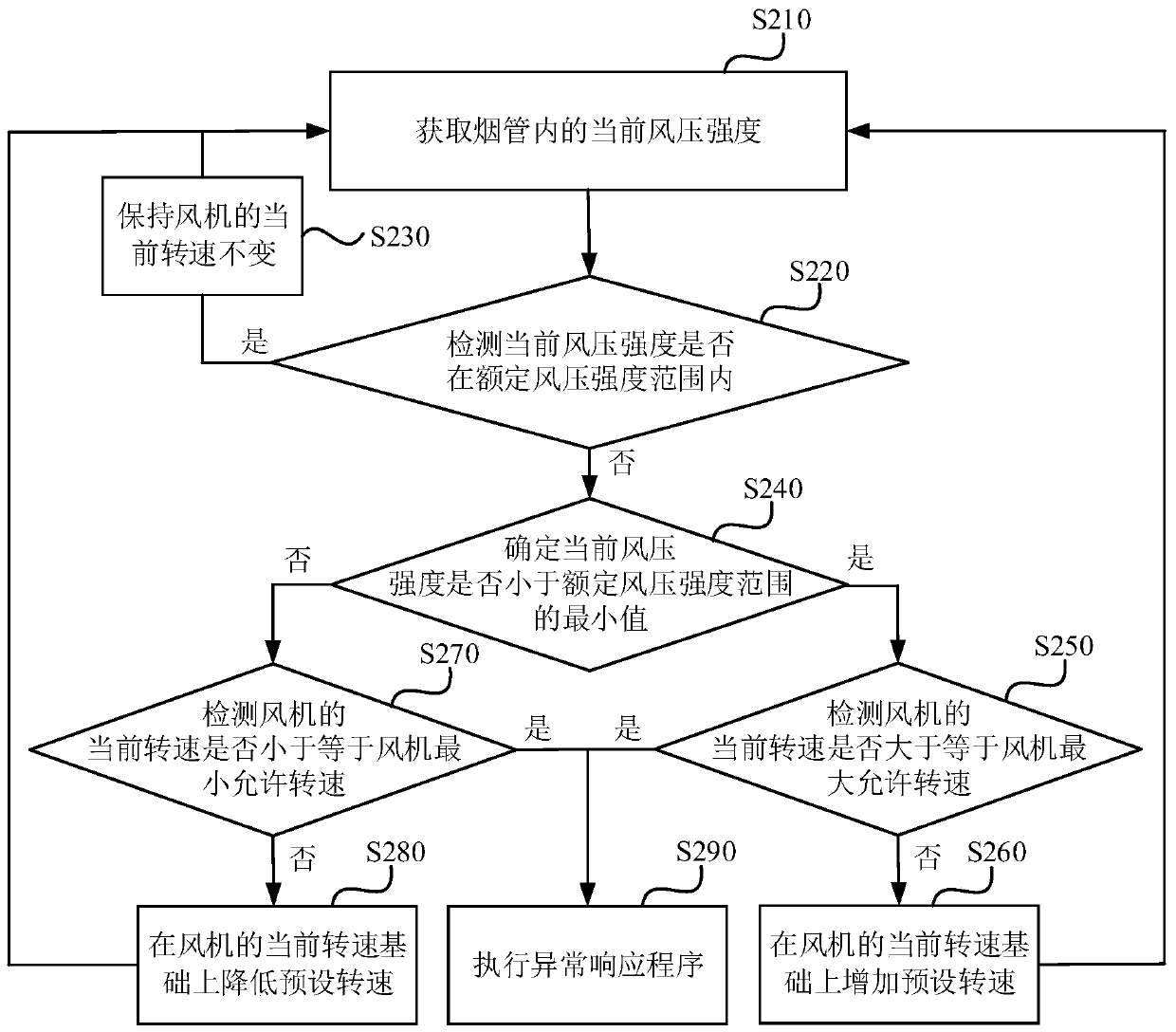
[0047] figure 2 It is a schematic flowchart of a wind pressure control method provided in Embodiment 2 of the present invention. This embodiment is optimized on the basis of the above-mentioned embodiments, and provides a preferred wind pressure control method. Specifically, if it is determined that the current wind pressure intensity is less than the minimum value of the rated wind pressure intensity range, then increase the wind pressure on the basis of the current speed of the fan. The preset speed is further optimized to include: if it is determined that the current wind pressure intensity is less than the minimum value of the rated wind pressure intensity range, then detecting whether the current speed of the fan is greater than or equal to the maximum allowable speed of the fan; if it is determined that the current speed of the fan is greater than or equal to the maximum allowable speed of the fan If it is determined that the current speed of the fan is lower than the m...

Embodiment 3

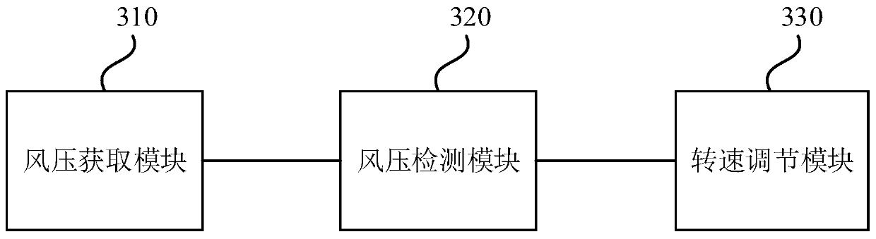
[0067] image 3 It is a schematic structural diagram of a wind pressure control device provided in Embodiment 3 of the present invention. refer to image 3 , the wind pressure control device includes: a wind pressure acquisition module 310, a wind pressure detection module 320, and a rotation speed adjustment module 330, each module will be described in detail below.

[0068] A wind pressure acquisition module 310, configured to acquire the current wind pressure intensity in the smoke pipe;

[0069] A wind pressure detection module 320, configured to detect whether the current wind pressure intensity is within the rated wind pressure intensity range;

[0070] The rotation speed adjustment module 330 is configured to adjust the current rotation speed of the blower fan if it is determined that the current wind pressure intensity is not within the rated wind pressure intensity range, and return to obtain the current wind pressure intensity in the smoke pipe to dynamically contr...


PUM


Abstract

The embodiment of the invention discloses a wind pressure control method, device and equipment and a storage medium. The method comprises the steps of obtaining current wind pressure strength in a smoke pipe; detecting whether the current wind pressure strength is within the range of rated wind pressure strength; and if it is determined that the current wind pressure strength is not within the range of the rated wind pressure strength, adjusting the current rotating speed of a fan, and returning to execute the operation of obtaining the current wind pressure strength in the smoke pipe so as todynamically control the wind pressure. According to the technical scheme, the wind pressure real-time adjusting is achieved, the control response speed is improved, and the wind pressure compensationprecision is improved.

Description

technical field [0001] The embodiments of the present invention relate to the technical field of water heater control, in particular to a wind pressure control method and device, a gas water heater and a storage medium. Background technique [0002] When the gas water heater is in a windy weather or the exhaust port of the flue is blocked, it is often difficult to ignite, ignite and deflagrate during the ignition process; in the normal combustion process, the combustion is inhibited and incomplete combustion occurs, resulting in excessive smoke emissions. Even the flame goes out after burning for a while. This is because when the outdoor wind pressure is too high, the difference between the wind pressure generated by the fan inside the flue pipe and the outside wind pressure becomes smaller, and the exhaust of the fan will be suppressed, resulting in insufficient air volume for combustion. [0003] In the prior art, wind pressure control is mainly realized by calculating an...

Claims


Application Information

Patent Timeline
IPC IPC(8): F24H9/20F23N3/00
CPCF23N3/002F24H9/2035
Inventor 李键孙运磊刘云寇福凯
Owner CHONGQING HAIER WATER HEATER
Why Eureka
Try Eureka