Vehicle pose correction method and device

A vehicle, pose technology, applied in the field of autonomous driving, can solve the problem of low positioning accuracy

Active Publication Date: 2020-04-03
BEIJING MOMENTA TECH CO LTD
View PDF8 Cites 12 Cited by
  • Summary
  • Abstract
  • Description
  • Claims
  • Application Information

AI Technical Summary

Problems solved by technology

[0005] The embodiment of the present invention discloses a method and device for correcting vehicle pose, which solves the problem of low positio...

Method used


Image

  • Vehicle pose correction method and device
  • Vehicle pose correction method and device
  • Vehicle pose correction method and device

Examples


Embodiment 1

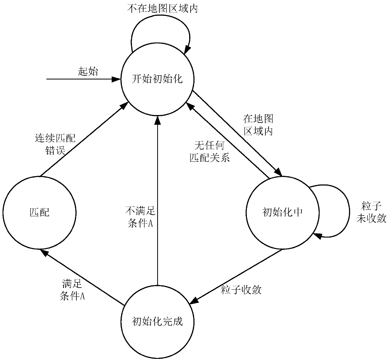
[0101] see Figure 2a , Figure 2a It is a schematic flowchart of a vehicle pose correction method provided by an embodiment of the present invention. This method is applied to automatic driving. This method is typically applied to the scene where the vehicle enters the area corresponding to the prior position covered by the preset navigation map for the first time. When the target is high, the correct target matching relationship between the perception image and the preset navigation map is generated, and the target matching relationship is used to optimize the vehicle body pose with centimeter-level positioning accuracy. The method provided in this embodiment can be executed by a device for correcting the vehicle pose, which can be realized by means of software and / or hardware, and can generally be integrated in a vehicle-mounted terminal such as a vehicle-mounted computer or a vehicle-mounted industrial personal computer (IPC). , the embodiments of the present invention a...

Embodiment 2

[0135] see Figure 3a , Figure 3a It is a schematic flowchart of a vehicle pose correction method provided by an embodiment of the present invention. On the basis of the above-mentioned embodiments, this embodiment optimizes the search process of the map elements projected onto the perception image. Such as Figure 3a As shown, the method includes:

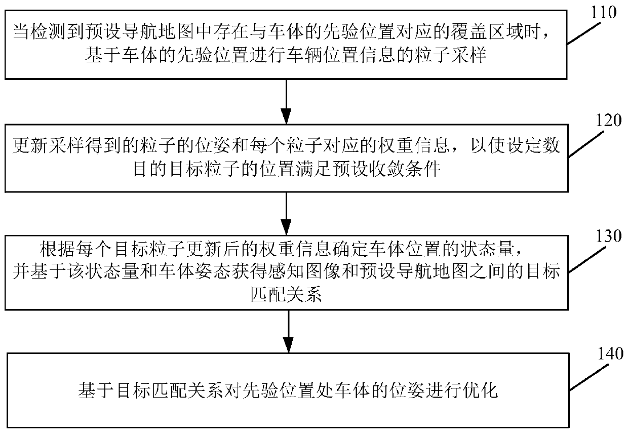
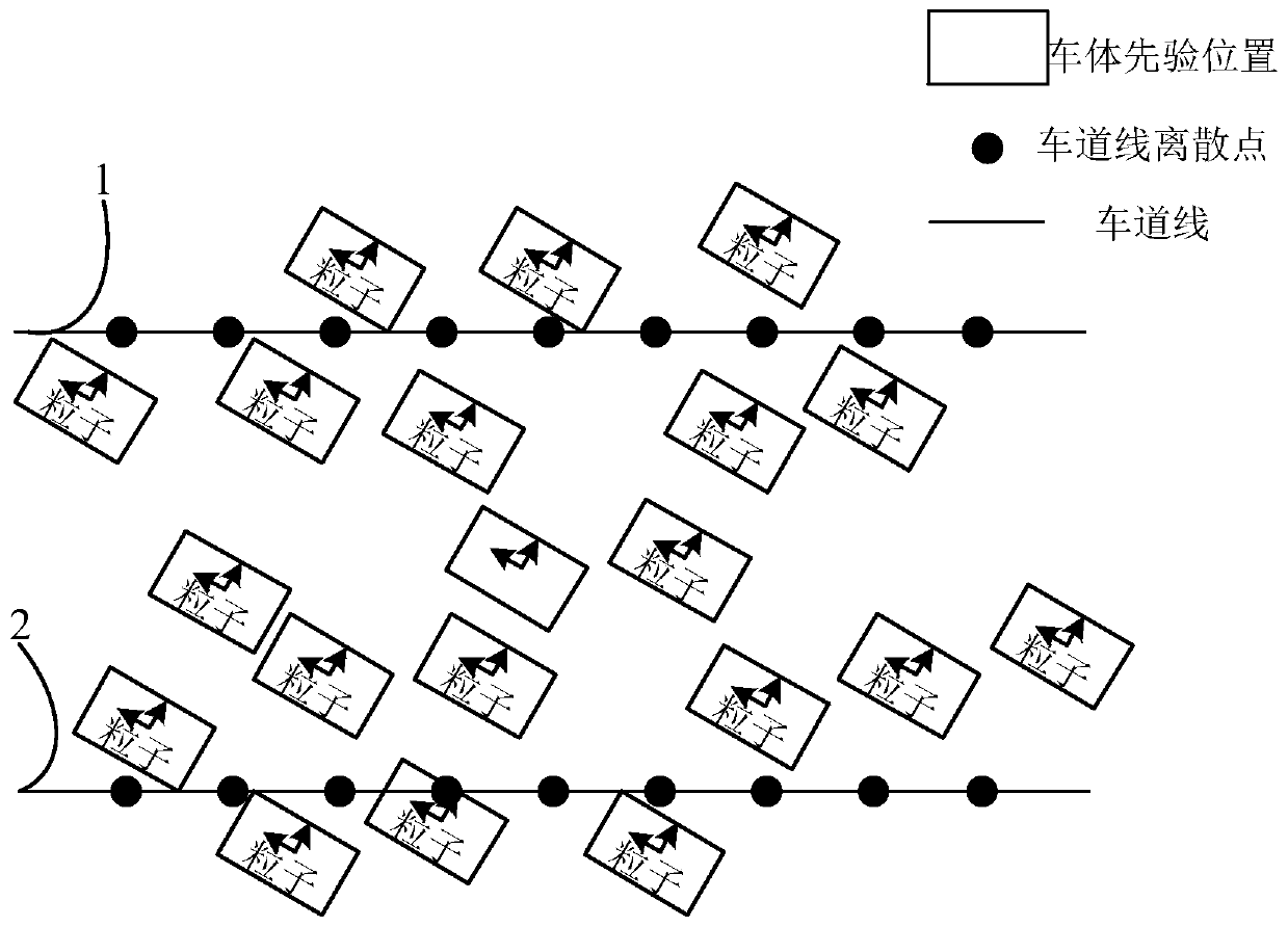
[0136] 210. When it is detected that there is a coverage area corresponding to the prior position of the vehicle body in the preset navigation map, perform particle sampling of the vehicle position information based on the prior position of the vehicle body.

[0137] 220. For any sampled particle, determine the position information of the particle at the current moment.

[0138] 230. Convert the map elements in the world coordinate system that meet the fourth set distance from the prior position of the vehicle body to the camera coordinate system.

[0139] Among them, the camera coordinate system is defined as the x-axis fac...

Embodiment 3

[0150] see Figure 4 , Figure 4 It is a schematic flowchart of a vehicle pose correction method provided by the embodiment of the present invention. On the basis of the above embodiments, this embodiment updates the weight information corresponding to each particle and the relationship between the perceived image and the preset navigation map. The establishment process of the target matching relationship has been optimized. Such as Figure 4 As shown, the method provided in this embodiment specifically includes:

[0151] 310. When it is detected that there is a coverage area corresponding to the prior position of the vehicle body in the preset navigation map, perform particle sampling of the vehicle position information based on the prior position of the vehicle body.

[0152] 320. Update the sampled particle poses and weight information corresponding to each particle, so that the positions of a set number of target particles meet a preset convergence condition.

[0153] ...


PUM


Abstract

The embodiment of the invention discloses a vehicle pose correction method and device, and the method comprises the steps of carrying out the particle sampling on the vehicle position information based on the prior position of a vehicle body when a coverage region corresponding to the prior position of the vehicle body is detected in a preset navigation map, wherein the prior position is obtainedthrough a preset positioning device; updating the poses of the particles obtained by sampling and the weight information corresponding to each particle so as to enable the positions of the target particles with the set number to meet a preset convergence condition; determining the state quantity of the vehicle body position according to the updated weight information of each target particle, and obtaining a target matching relationship between the perception image and the preset navigation map based on the state quantity and the vehicle body posture; and optimizing the pose of the vehicle bodyat the prior position based on the target matching relationship. By the adoption of the technical scheme, the problem that the positioning precision is not high when a consumer-level preset positioning device is used is solved, and the technical effect of the centimeter-level high-precision positioning of the vehicle is achieved.

Description

technical field [0001] The invention relates to the technical field of automatic driving, in particular to a method and device for correcting vehicle pose. Background technique [0002] In the field of autonomous driving, high-precision positioning is crucial. In recent years, the achievements of deep learning and other technologies have greatly promoted the development of image semantic segmentation and image recognition, which provides a solid foundation for high-precision maps and high-precision positioning. [0003] In the positioning scheme based on high-precision maps, when an unmanned vehicle enters the area covered by the preset navigation map and corresponds to the prior position for the first time, it needs to obtain a global and accurate position information for initialization, and then can Use high-precision maps for precise positioning, that is, the absolute position accuracy can reach centimeter level. However, in consumer-level equipment, such as single-poin...

Claims


Application Information

Patent Timeline
IPC IPC(8): G01C21/30G01C21/20G01C25/00
CPCG01C21/20G01C21/30G01C25/00
Inventor 李江龙穆北鹏
Owner BEIJING MOMENTA TECH CO LTD
Why Eureka
Try Eureka