Battery detection power supply, and output control method and device
A technology for battery detection and output control, applied in battery circuit devices, measuring devices, circuit devices, etc.
- Summary
- Abstract
- Description
- Claims
- Application Information
AI Technical Summary
Problems solved by technology
Method used
Image
Examples
Embodiment 1
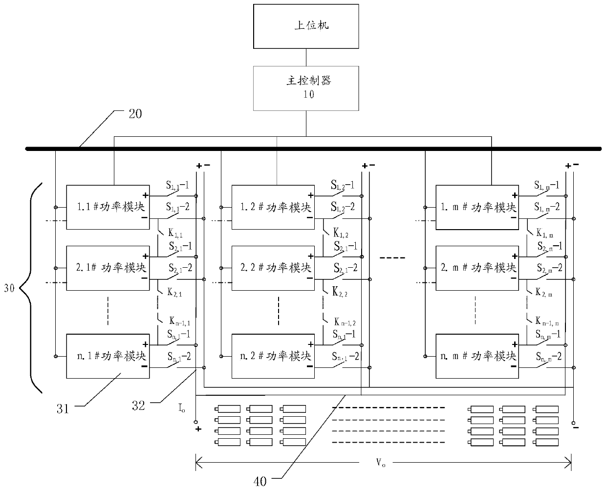
[0035] figure 1 It is a schematic diagram of a battery detection power supply according to an embodiment of the present application.
[0036] Such as figure 1 As shown, the battery detection power supply provided by this embodiment includes a main controller 10 , a DC bus 20 , a DC / DC module array 30 and an output bus 40 . The main controller is signal-connected with the host computer and the DC / DC module array respectively, and the DC / DC module array is electrically connected with the DC bus and the output bus respectively.
[0037] Wherein, the main controller 1 is used to receive the configuration file sent by the upper computer, the configuration file includes output voltage parameters and output current parameters, including one of the output voltage parameters and output current parameters. Analyze the configuration file after receiving it, and output switch control instructions to the DC / DC module array according to the analysis result and the array working mode input...
Embodiment 2
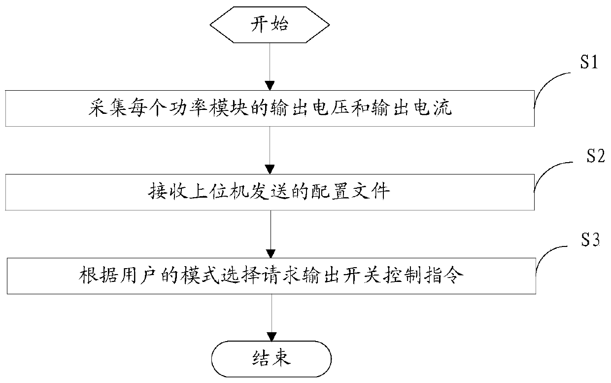
[0046] figure 2 It is a flow chart of an output control method in an embodiment of the present application.
[0047] Such as figure 2 As shown, the output control method provided in this embodiment is applied to the battery detection power supply in the previous embodiment. The output control method includes the steps of:
[0048] S1. Collect the output voltage and output current of each power module.
[0049] It is also possible to collect only the output voltage or output current of the power module in some cases, and the output voltage and output current of each power module are V i,j / I i,j (i=1,2,...,n, j=1,2,...,m), and further calculate the total voltage V o and total current I o .
[0050] S2. Receive the configuration file sent by the host computer.
[0051] Through the analysis of the configuration file, the corresponding output voltage parameters and output current parameters can be obtained.
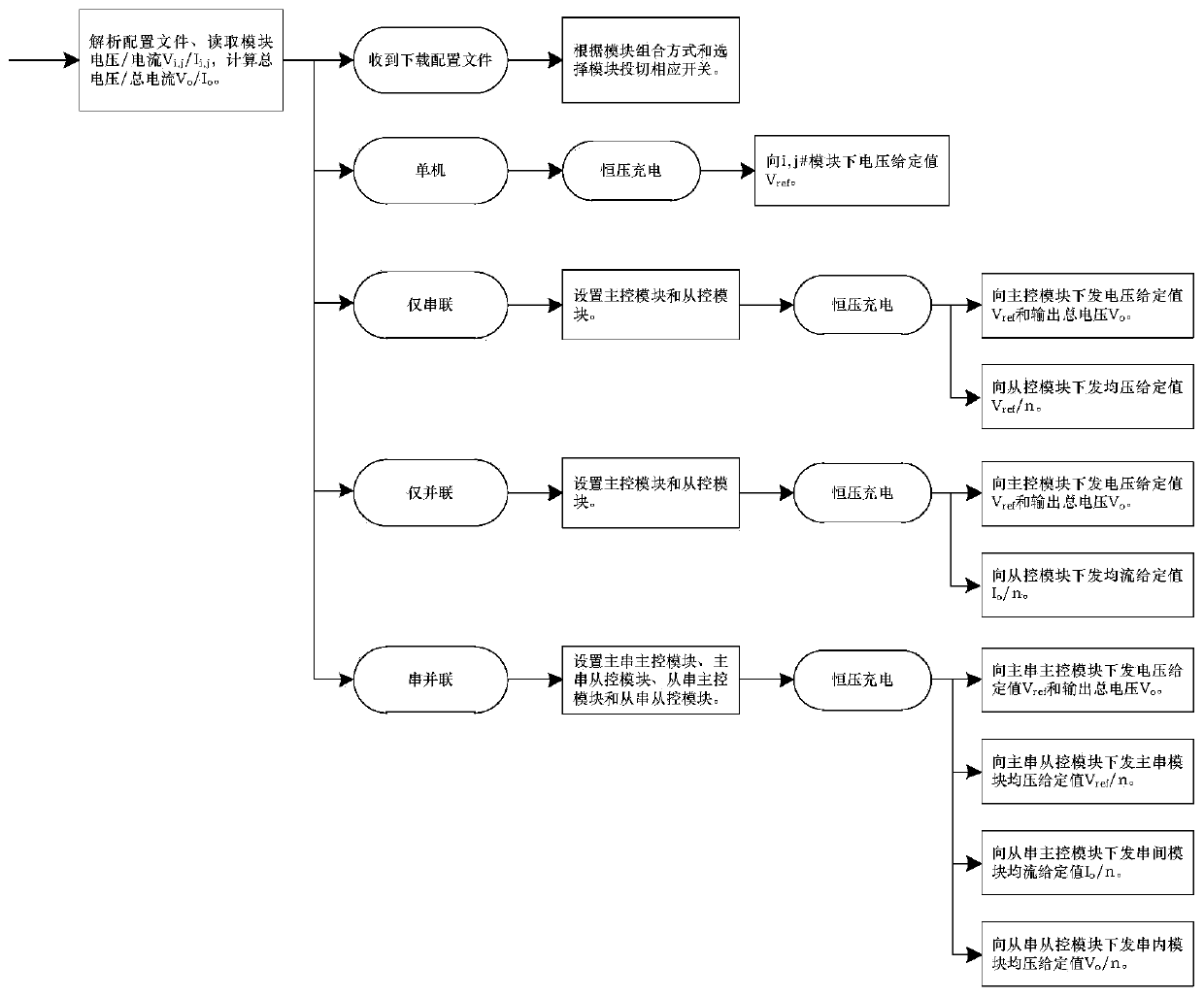
[0052] S3. Outputting a switch control instruction according ...
Embodiment 3
[0068] Figure 5 It is a block diagram of an output control device according to an embodiment of the present application.
[0069] Such as Figure 5 As shown, the output control device provided in this embodiment is applied to the main controller of the battery detection power supply provided in this application, and the output control device includes a parameter acquisition module 50 , a file receiving module 60 and an instruction output module 70 .
[0070] The parameter collection module is used to collect the output voltage and output current of each power module.
[0071] It is also possible to collect only the output voltage or output current of the power module in some cases, and the output voltage and output current of each power module are V i,j / I i,j (i=1,2,...,n, j=1,2,...,m), and further calculate the total voltage V o and total current I o .
[0072] The file receiving module is used to receive the configuration file sent by the host computer.
[0073] Thr...
PUM
 Abstract
Description
Claims
Application Information
 - R&D
- Intellectual Property
- Life Sciences
- Materials
- Tech Scout
- Unparalleled Data Quality
- Higher Quality Content
- 60% Fewer Hallucinations
Browse by: Latest US Patents, China's latest patents, Technical Efficacy Thesaurus, Application Domain, Technology Topic, Popular Technical Reports.
© 2025 PatSnap. All rights reserved.Legal|Privacy policy|Modern Slavery Act Transparency Statement|Sitemap|About US| Contact US: help@patsnap.com


