Service transmission method and device

A technology for service transmission and resource transmission, applied in the field of service transmission methods and devices

Active Publication Date: 2020-04-03
ZTE CORP
View PDF7 Cites 2 Cited by
  • Summary
  • Abstract
  • Description
  • Claims
  • Application Information

AI Technical Summary

Problems solved by technology

[0003] Embodiments of the present invention provide a service transmission method and device to at least solve the problem of how to ensure service delay requirements in related technologies

Method used


Image

  • Service transmission method and device
  • Service transmission method and device
  • Service transmission method and device

Examples


Embodiment 1

[0084] In this embodiment, an application server (Application Server) needs to send an instruction of a fixed service transmission mode to a UE in RRC_Inactive (idle state). Such as Figure 4 shown, including the following steps:

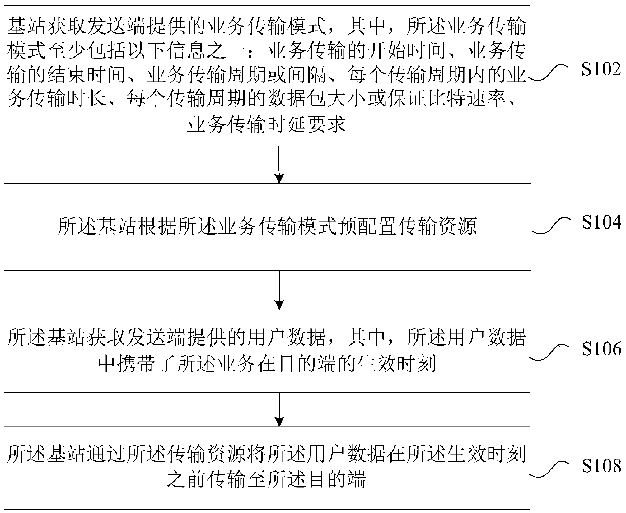
[0085] Step 1: At time T0, the application server (Application Server, AS) sends the user data and service transmission mode to the access and mobility management function entity (Access and Mobility Management Function, AMF) / user plane function entity (User Plane Function, UPF); the service transmission mode may include the start time of the service transmission and / or the end time of the service transmission, the service transmission period or interval, the service transmission duration in each transmission period, the data packet size of each transmission period or Guaranteed Bit Rate (GBR), service transmission delay requirements; the user data carries the effective time of the service at the destination.

[0086] Step 2: The AMF / UPF functiona...

Embodiment 2

[0129] Image 6 It is an implementation example of service transmission for a service with a fixed service mode. In this embodiment, an application server (Application Server) needs to send a set of instructions with a fixed service mode to a UE in a connected state.

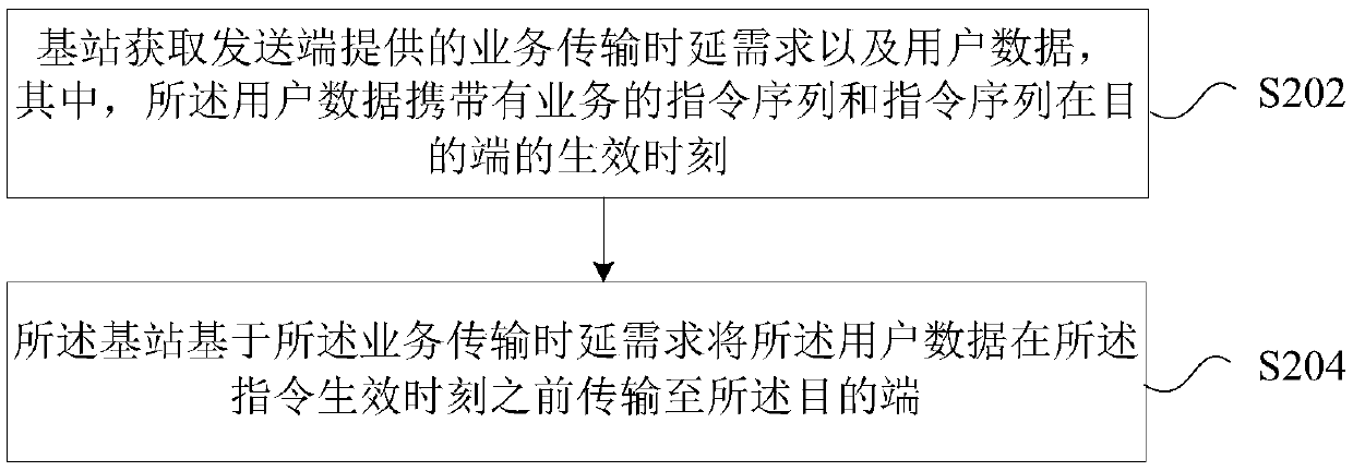
[0130] Step 1: At time T0, the application server sends user data information carrying several instruction sequences to the AMF / UPF;

[0131] Step 2: AMF / UPF transmits the user data information including the instruction sequence to gNB;

[0132] Step 3: The gNB transmits the user data information including the instruction sequence to the UE at time T1;

[0133] Step 3: At time T2, the first instruction contained in the user data information takes effect according to the time point indicated in the instruction; at time T3, the second instruction contained in the user data information takes effect according to the time point indicated in the instruction; at time T4 , the third instruction included in the user da...

Embodiment 3

[0137] Figure 8 It is an implementation example of service transmission for a service whose transmission mode is not fixed. In this embodiment, the application server sends an instruction that the service transmission mode is not fixed to the UE in the connected mode. Such as Figure 8 shown, including the following steps:

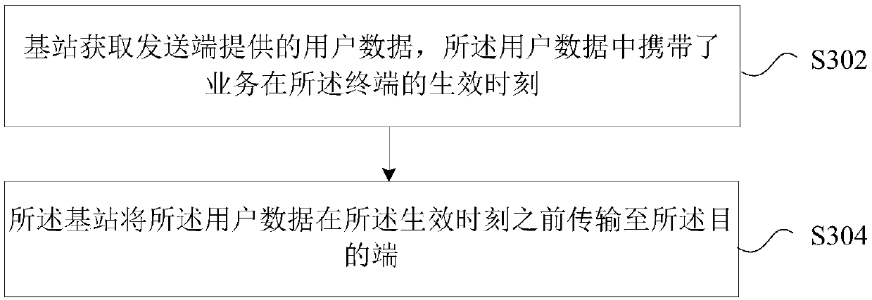
[0138] Step 1: At time T0, the application server sends user data to AMF / UPF;

[0139]Step 2: AMF / UPF sends data packet delay requirements to gNB, and the requirements can be carried in PDU SESSIONRESOURCE SETUP REQUEST or similar messages between the base station and the core network;

[0140] Step 3: gNB sends a response message of packet delay requirement to AMF / UPF, the message can be PDUSESSION RESOURCE SETUP RESPONSE or a similar message between the base station and the core network;

[0141] Step 4: AMF / UPF sends user data to gNB;

[0142] Step 5: gNB sends user data to UE;

[0143] Step 6: At time T1, the UE responds based on the instruction ...


PUM


Abstract

The invention provides a service transmission method and device. The method comprises the following steps: a base station acquires a service transmission mode provided by a sending end, wherein the service transmission mode at least comprises one of the following information: start time of service transmission, end time of service transmission, service transmission periods or intervals, service transmission duration in each transmission period, data packet size or guaranteed bit rate of each transmission period, and service transmission delay requirements; the base station pre-configures transmission resources according to the service transmission mode; the base station acquires user data provided by the sending end, wherein the user data carries an effective moment of the service at a destination end; and the base station transmits the user data to the destination end before the effective moment through the transmission resource. According to the invention, the corresponding transmission resources are pre-configured for the terminal according to the service transmission mode, so that the service transmission time delay among the nodes can be controlled, and it is ensured that theservice reaches the destination end before the destination end takes effect.

Description

technical field [0001] The present invention relates to the communication field, in particular to a service transmission method and device. Background technique [0002] In the Industrial Internet of Things (IIoT) system, the IIoT business generally transmits machine instructions, and the delay sensitivity of the business is very high, usually reaching the microsecond level. However, in the current wireless communication system, service transmission involves transmission between multiple nodes. For example, service transmission between terminals is generally: the terminal transmits to the base station, the base station transmits to the core network, the core network transmits to the target base station, and the target base station transmits to the target terminal. The service transmission from the application server to the terminal is generally as follows: the application server transmits it to the core network, the core network transmits it to the base station, and the bas...

Claims


Application Information

Patent Timeline
Patent Type & Authority Applications(China)
IPC IPC(8): H04W56/00H04W72/04H04W72/12H04W72/08
CPCH04W56/001H04W56/0045H04W56/009H04W72/04H04W72/1273H04W72/543H04W72/23H04W4/06H04J3/0658H04W28/0268
Inventor 沙秀斌戴博陆婷高音
Owner ZTE CORP
Why Eureka
Try Eureka