An agricultural weeding device for synchronous removal of grass clippings
An agricultural and grass clipping technology, applied in the field of agricultural weeding, can solve the problems of increased labor cost, poor grass cutting and grass clipping removal effect, etc., and achieves the effect of improving the effect, the best cutting effect and the storage effect.
- Summary
- Abstract
- Description
- Claims
- Application Information
AI Technical Summary
Problems solved by technology
Method used
Image
Examples
Embodiment 1
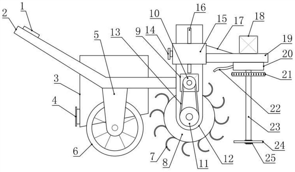
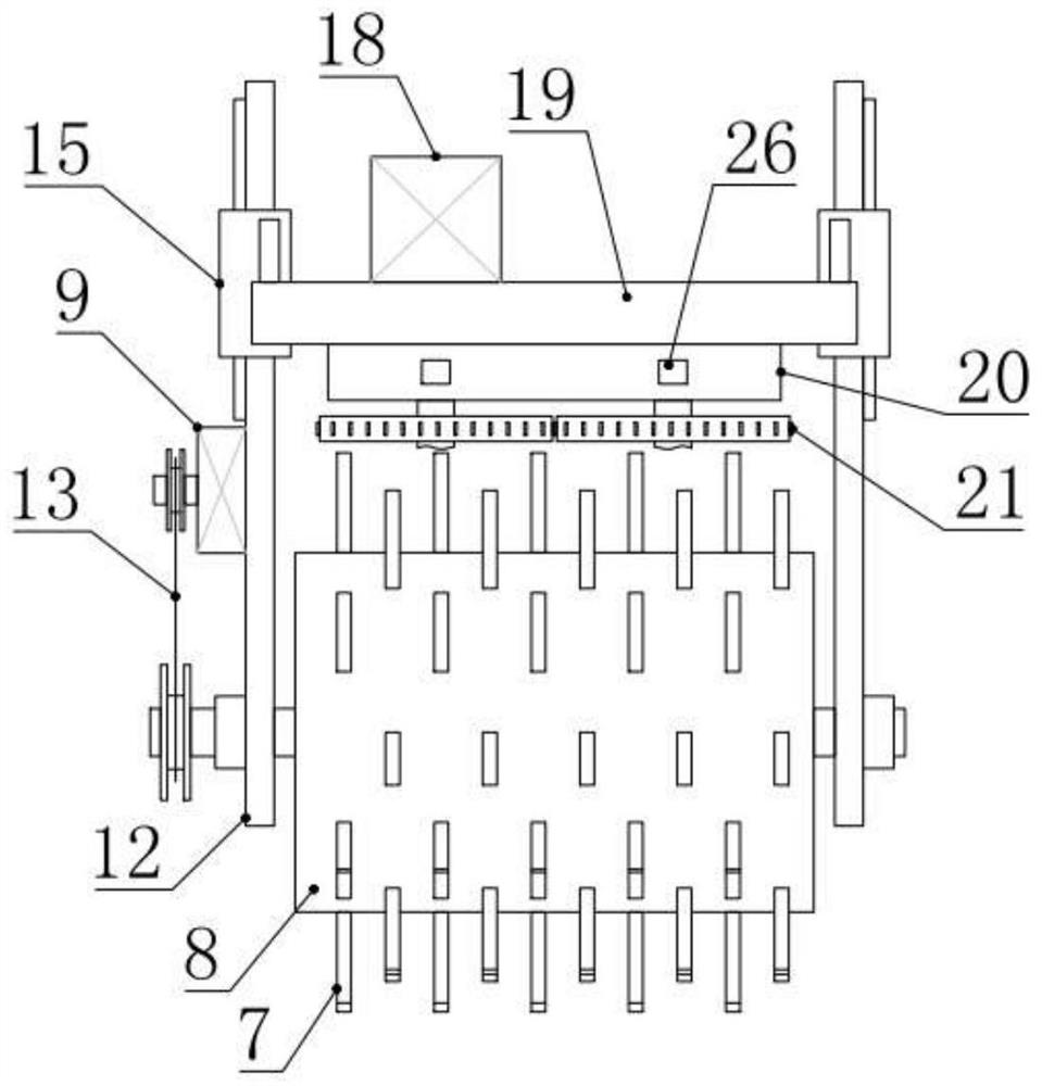
[0020] see Figure 1-3 , 5, in the embodiment of the present invention, a kind of grass cuttings synchronous removal type agricultural weeding device, comprises handrail 2, wheel frame 5, walking wheel 6 and mowing knife 24, and the underside of described handrail 2 is installed with wheel frame 5 The walking wheel 6 facilitates the movement of the device. Two side frames 12 are installed and fixed on the end of the handrail 2, and the grass wheel 8 is installed on the bottom of the two side frames 12, and the grass wheel 8 passes through the side frame. The first driving mechanism installed on the 12 is driven to rotate, and some weeding rods 7 are also circumferentially installed on the weeding wheel 8 .
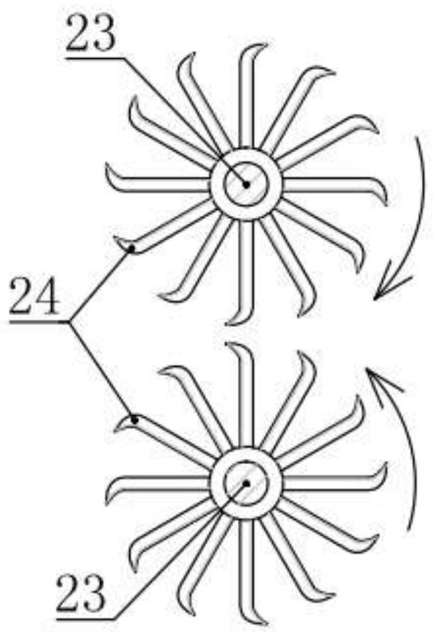
[0021] The two side frames 12 are straddled with a mounting frame 19 that can be adjusted up and down. The underside of the mounting frame 19 is provided with two rotating rods 23, and the mounting frame 19 is also provided with two rotating rods for driving. The second d...
Embodiment 2
[0030] see Figure 1-2 , 4, the difference between this embodiment and embodiment 1 is:
[0031] In this embodiment, a blower box 20 is installed and fixed on the lower side of the installation frame 19, the inner cavity of the blower box 20 is a wind chamber 29, and two rotating rods 23 are arranged through the upper and lower surfaces of the blower box 20, And two described rotating rods 23 are connected with airtight rotation of blower box 20, on two rotating rods 23 in described blower box 20, an impeller 27 is installed and fixed respectively, and impeller 27 adopts existing technical structure, as figure 2 As shown, the right side of the blower box 20 is provided with air intake holes 26 corresponding to two impellers 27, as Figure 4 As shown, the left middle part of the blower box 20 is provided with an air outlet 28, and the impeller 27 is used to suck the outside air from the air inlet 26 into the air chamber 29 and discharge it through the air outlet 28. The air ...
PUM
 Abstract
Description
Claims
Application Information
 - R&D
- Intellectual Property
- Life Sciences
- Materials
- Tech Scout
- Unparalleled Data Quality
- Higher Quality Content
- 60% Fewer Hallucinations
Browse by: Latest US Patents, China's latest patents, Technical Efficacy Thesaurus, Application Domain, Technology Topic, Popular Technical Reports.
© 2025 PatSnap. All rights reserved.Legal|Privacy policy|Modern Slavery Act Transparency Statement|Sitemap|About US| Contact US: help@patsnap.com


