Integrated joint of oil running oscillating cylinder
A swing cylinder and joint technology, applied in the field of robotics, can solve the problems of insufficient driving torque of robot joints and small load torque, and achieve the effects of compact structure, reduced wear and tear, and improved safety and reliability
- Summary
- Abstract
- Description
- Claims
- Application Information
AI Technical Summary
Problems solved by technology
Method used
Image

Examples
specific Embodiment approach 1
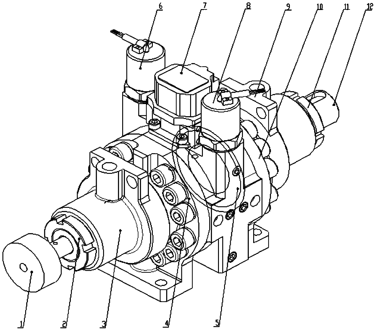
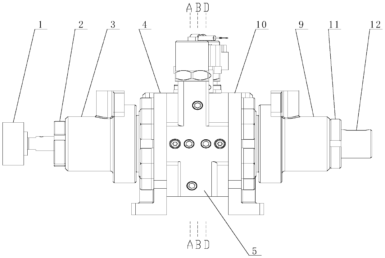
[0017] Specific implementation mode one: combine figure 1 with figure 2 Describe the present embodiment. The integrated joint of the oil-carrying swing cylinder described in the present embodiment includes a first round nut 2, a left actuator 3, a left cylinder head 4, a cylinder body 5, a right actuator 9, and a right cylinder head 10. , the second round nut 11 and the output shaft 12, the cylinder body 5 is set on the middle part of the output shaft 12, the first round nut 2, the actuator 3 and the left cylinder head 4 are set on the left end of the output shaft 12 from left to right in turn, the second Two round nuts 11, the right actuator 9, and the right cylinder head 10 are set on the right end of the output shaft 12 successively from right to left.
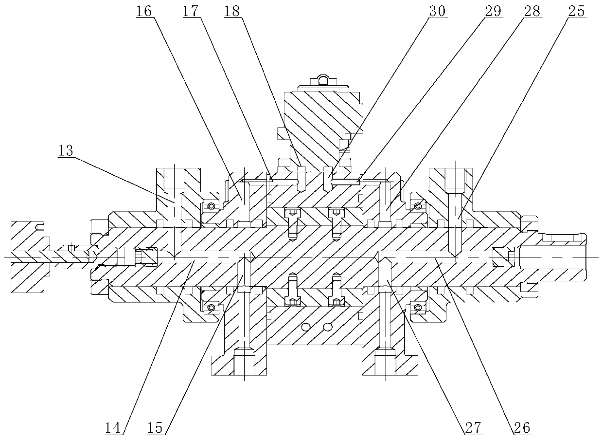
[0018] In this embodiment, vanes 5-1 are arranged symmetrically up and down in the cylinder body 5, and baffles 5-2 are arranged symmetrically in the cylinder body 5 left and right. The joint rotation is realized by the ...
specific Embodiment approach 2
[0019] Specific implementation mode two: combination figure 1 with figure 2 To describe this embodiment, the joint with an integrated oil traveling and swinging cylinder described in this embodiment further includes an angle sensor 1 , and the angle sensor 1 is installed on the left end of the output shaft 12 . Other components and connections are the same as those in the first embodiment.
specific Embodiment approach 3
[0020] Specific implementation mode three: combination figure 1 with figure 2 To describe this embodiment, the joint with integrated oil traveling and swing cylinder described in this embodiment further includes a servo valve 7 installed on the upper surface of the cylinder body 5 . Other components and connections are the same as those in the first embodiment.
PUM
 Abstract
Description
Claims
Application Information
 - Generate Ideas
- Intellectual Property
- Life Sciences
- Materials
- Tech Scout
- Unparalleled Data Quality
- Higher Quality Content
- 60% Fewer Hallucinations
Browse by: Latest US Patents, China's latest patents, Technical Efficacy Thesaurus, Application Domain, Technology Topic, Popular Technical Reports.
© 2025 PatSnap. All rights reserved.Legal|Privacy policy|Modern Slavery Act Transparency Statement|Sitemap|About US| Contact US: help@patsnap.com