Pressing self-locking structure and pressing pen adopting same

A technology of self-locking structure and matching structure, which is applied in printing, writing utensils, writing parts, etc., can solve problems such as energy waste, oil leakage, and pen head wear, and achieve simple and convenient operation, strong flexibility, and reduce unnecessary troublesome effect

Active Publication Date: 2020-04-07
HANGZHOU JIANYI TECHNOLOGY CO LTD
View PDF5 Cites 1 Cited by
  • Summary
  • Abstract
  • Description
  • Claims
  • Application Information

AI Technical Summary

Problems solved by technology

[0003] The existing push self-locking structure usually only needs to use a small force to trigger the push button for convenience during use. When the button is accidentally touched during use, the entire device will start. When the switch button is used, it will easily lead to unnecessary waste of energy consumption, and for young children, they often press the switch button of life back and forth repeatedly. Too many times of pressing will easily reduce the service life of the pen. In the process of using or carrying, when foreign objects accidentally press the pressing part at the rear end of the press pen, it is easy to expose the pen head of the pen core, and then the pen oil is easy to be contaminated on the external objects, and at the same time, the external objects are also easy to cause wear on the pen head, which may cause damage to the pen. The drop of the pen ball causes oil leakage during writing

Method used


Image

  • Pressing self-locking structure and pressing pen adopting same
  • Pressing self-locking structure and pressing pen adopting same
  • Pressing self-locking structure and pressing pen adopting same

Examples


Embodiment 1

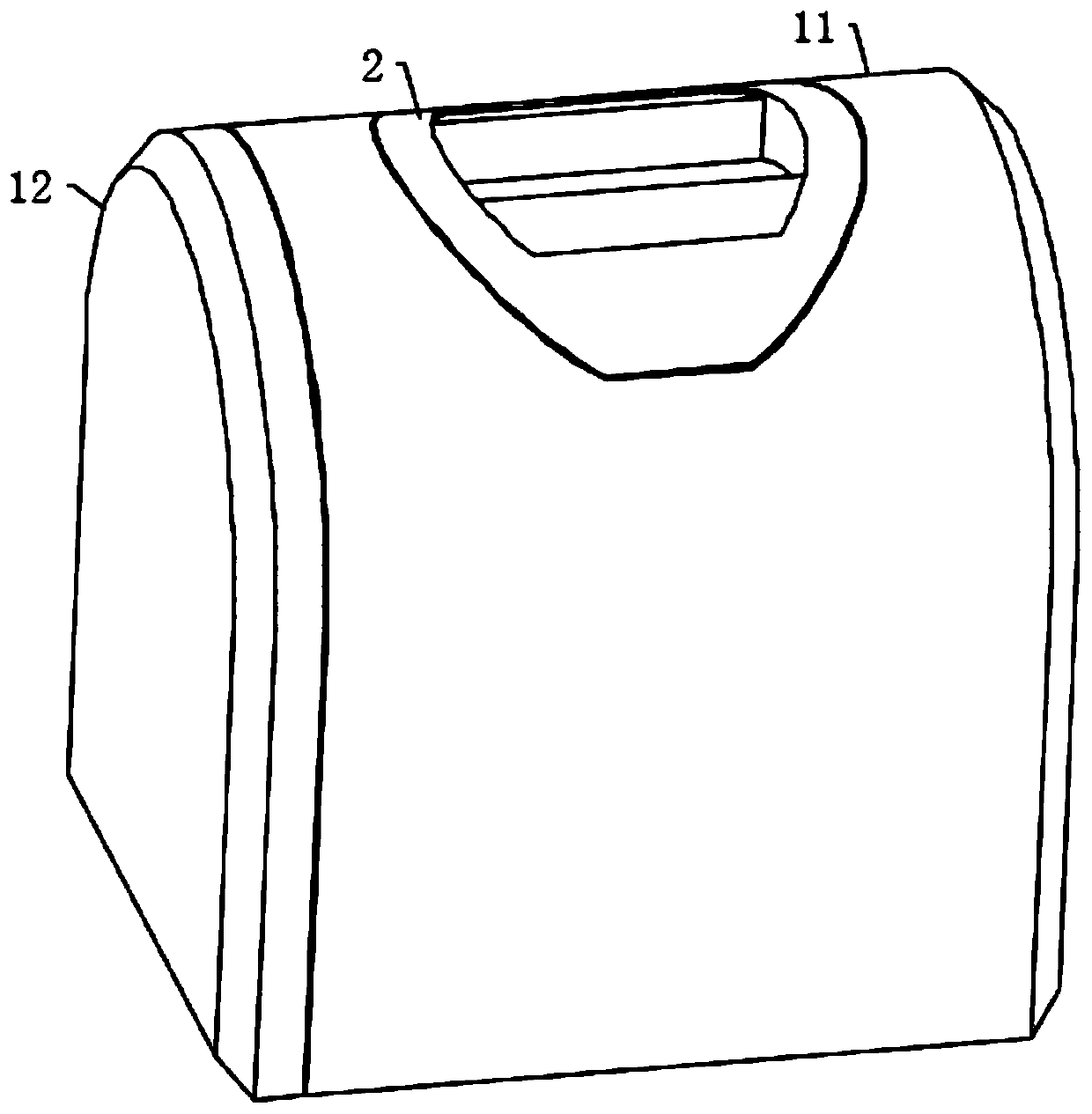
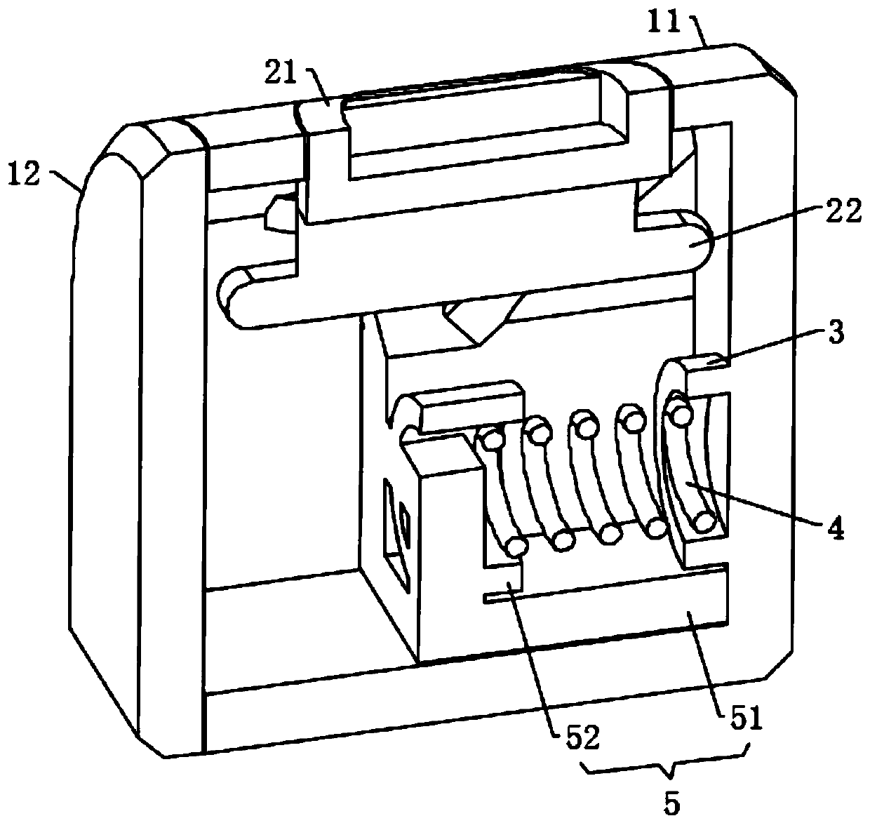
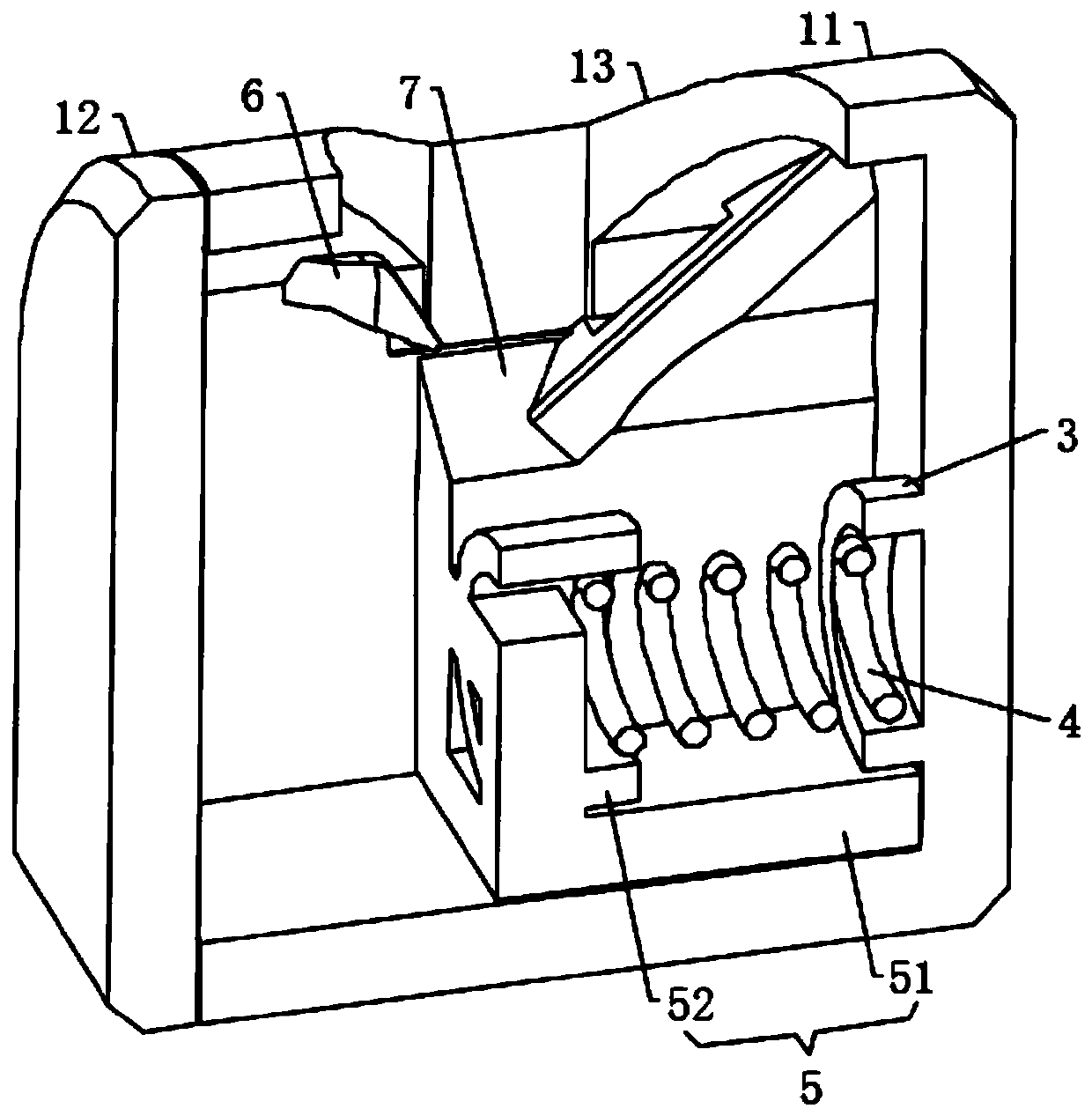
[0049] see Figure 1-8 , a push-to-lock structure, see Figure 1-2 , comprising a left frame body 11 and a right frame body 12 fixed on the rear portion of the left frame body 11, the inside of the left frame body 11 is provided with a sliding connector 5, and the sliding connector 5 is externally connected to an external component during use, and the left frame body 11 3 is fixed on the inner wall of the front part, and a return spring 4 is sleeved between the sliding connector 5 and 3. The sliding connector 5 includes a slider 51 that is slidably connected to the inner bottom of the left frame body 11 and is fixed on the slider 51. The annular positioning block 52 at the front, the return spring 4 is located between the annular positioning block 52 and 3, the slider 51 is located on the lower side of the limiter 6, and the slider 51 is on the left side of the frame when the pressing member 2 is pressed down once. 11 and move forward, while the annular positioning block 52 s...


PUM


Abstract

The invention discloses a pressing self-locking structure, which belongs to the technical field of pressing self-locking. The pressing self-locking structure comprises a left frame body and a right frame body fixedly arranged at the rear part of the left frame body, wherein a sliding connecting piece is arranged in the left frame body; the inner wall of the front part of the left frame body is fixedly provided with a barrel; a return spring is sleeved between the sliding connecting piece and the barrel; the upper part of the left frame body is provided with a pressing piece for driving the sliding connecting piece to axially and relatively slide in the left frame body; axial movement of the sliding connecting piece in the right frame body can be realized by pressing the pressing piece; andfurther, the sliding connecting piece is promoted to drive an external part to move, and a use state and a non-use state of the external part can be realized. The operation is simple and convenient,the flexibility is stronger, and the pressing piece is not easy to move downwards in the right frame body when the external acting force is smaller, so that the triggering of the whole device is not easy to cause, the device is kept in the non-use state, and unnecessary troubles caused by external mistaken touch are reduced.

Description

technical field [0001] The invention relates to the technical field of push self-locking, more specifically, to a push self-locking structure. Background technique [0002] The push self-locking structure is used in all aspects of life, such as socket switch, push flashlight switch, push writing pen, etc. [0003] In order to facilitate the use, the existing push self-locking structure usually only needs to use a small force to trigger the push button. When the button is accidentally touched during use, the whole device will start. When the switch button is used, it will easily lead to unnecessary waste of energy consumption, and for young children, they often press the switch button of life back and forth repeatedly. Too many times of pressing will easily reduce the service life of the pen. When using or carrying an external item accidentally pressing the pressing part at the rear end of the pen, it is easy to expose the pen tip of the pen core, and then the pen oil is eas...

Claims


Application Information

Patent Timeline
Patent Type & Authority Applications(China)
IPC IPC(8): B43K24/08
CPCB43K24/082
Inventor 余成鹏
Owner HANGZHOU JIANYI TECHNOLOGY CO LTD
Why Eureka
Try Eureka