
Drive-by-wire hydraulic brake control system and control method thereof for automatic driving

A technology of automatic driving and hydraulic braking, which is applied in the direction of braking safety system, brake, foot-operated starting device, etc. It can solve the problems of affecting the driver's feeling, the limitation of the motor pump, and the driver's easy perception of vibration.

Inactive Publication Date: 2021-02-05
JILIN UNIV
View PDF5 Cites 0 Cited by
  • Summary
  • Abstract
  • Description
  • Claims
  • Application Information

AI Technical Summary

Problems solved by technology

[0004] In the above scheme, when the motor and the transmission mechanism fail to be used, the motor pump is used for redundancy, but the motor pump is limited by the current technology, and it cannot be used for a long time, and the above configuration has a hydraulic shock when the brake is decompressed The generated vibration is transmitted to the vehicle's front cabin fender, and the driver can easily perceive the vibration, which affects the driver's feeling

Method used


Image

  • Drive-by-wire hydraulic brake control system and control method thereof for automatic driving
  • Drive-by-wire hydraulic brake control system and control method thereof for automatic driving
  • Drive-by-wire hydraulic brake control system and control method thereof for automatic driving

Examples


specific Embodiment approach

[0113] In order to clearly and completely describe the technical solution of the present invention and its specific working process, in conjunction with the accompanying drawings, the specific implementation of the present invention is as follows:

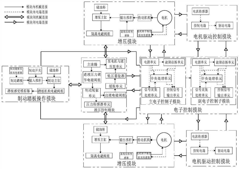
[0114] Such as figure 1 As shown, the present invention discloses a wire-controlled hydraulic brake control system for automatic driving, including: a set of brake pedal operation modules, a set of hydraulic control modules, two sets of booster modules, two sets of motor drive control modules and A set of electronic control modules.

[0115] The brake pedal operation module includes: brake pedal, brake pedal displacement dual sensors, input push rod, brake switch, brake master cylinder, pedal mechanism solenoid valve group, pedal feeling simulator and oil storage cup; wherein:

[0116] The brake pedal is mechanically connected to the brake master cylinder through the input push rod, which converts the kinetic energy of the brake p...


PUM


Abstract

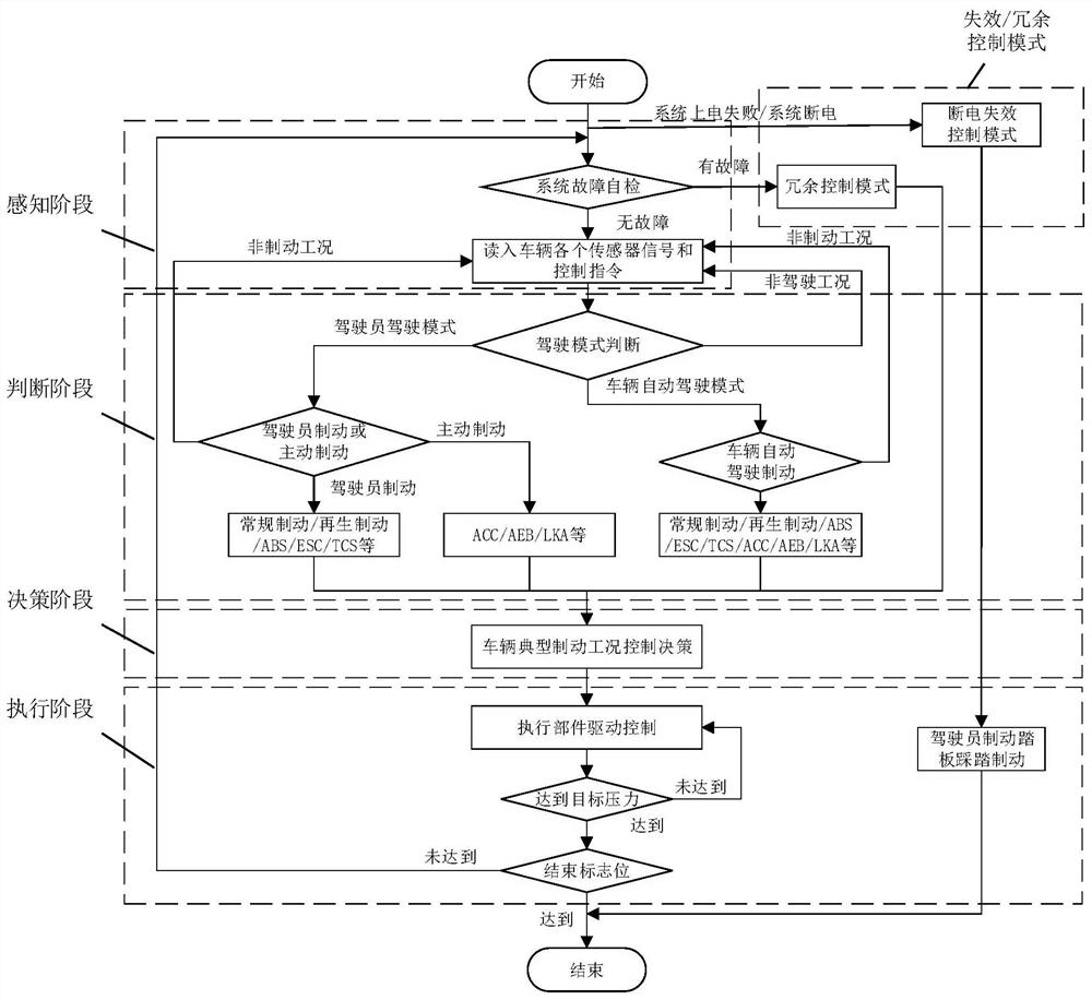
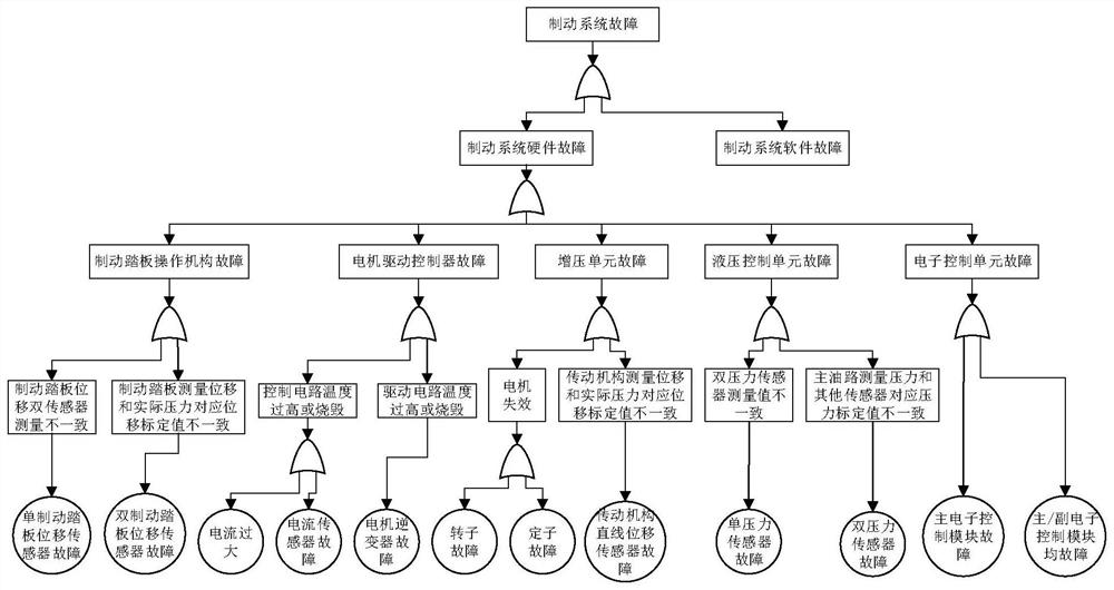
The invention provides a wire-controlled hydraulic brake control system and its control method for automatic driving. The system includes a set of brake pedal operation modules, a set of hydraulic control modules, two sets of booster modules, and two sets of motor drive control modules. and a set of electronic control modules, the brake pedal operation module and the booster module are respectively connected to the hydraulic control module pipeline, two sets of booster modules realize redundant backup, the brake pedal operation module, booster module, motor drive control module, The hydraulic control modules are respectively connected to the electronic control module by signal, and the electronic control module is composed of two groups of electronic control sub-modules to realize redundant backup; the control method includes: the brake control method in the power-on state without failure, typical hardware failure The braking control method under the following conditions and the braking control method under the failure state of power failure. The present invention adopts a redundant architecture of multiple booster modules, multiple sensors and multiple electronic control modules to meet the requirements of high-level automatic driving for the braking control system.

Description

technical field [0001] The invention belongs to the technical field of brake-by-wire for intelligent electric vehicles or intelligent networked vehicles, and in particular relates to an automatic-driving-oriented hydraulic brake-by-wire control system and a control method thereof. Background technique [0002] With the current development of intelligent networked vehicle technology, the automatic driving functions of L1 and L2 levels of new energy vehicles have become more and more mature, and the automatic driving technology of L3 level and above is gradually being developed. Brake-by-wire systems have initially begun to be explored. The brake-by-wire brake system for automatic driving at level L3 and above needs to be able to realize redundant control of the brake system, that is, after the brake system fails, the brake system can still ensure that the vehicle has good braking performance, and at the same time The system also needs to meet the requirements of various work...

Claims


Application Information

Patent Timeline
Patent Type & Authority Patents(China)
IPC IPC(8): B60T7/04B60T8/40B60T13/14B60T13/74B60T13/68B60T13/66B60T8/32B60T8/48B60T17/22
CPCB60T7/042B60T8/3265B60T8/409B60T8/4872B60T13/146B60T13/147B60T13/662B60T13/686B60T13/745B60T17/22
Inventor 李静张振兆
Owner JILIN UNIV
Learn More