Electronic mechanical hydraulic brake, braking control method and electronic hydraulic brake-by-wire system

A hydraulic brake, electronic machinery technology, applied in the direction of brake, brake transmission, transportation and packaging, etc., can solve problems such as the inability to guarantee the braking capacity of the vehicle, the inability of the wheels to maintain the braking force, affecting the safety of the vehicle, etc., and achieve a compact structure. , easy to operate, ensure the effect of safety

Pending Publication Date: 2019-04-19
JILIN UNIV
View PDF9 Cites 4 Cited by
  • Summary
  • Abstract
  • Description
  • Claims
  • Application Information

AI Technical Summary

Problems solved by technology

However, the layout of the wire-controlled hydraulic brake system still requires more hydraulic pipelines, such as the "dual-rotor motor wire-controlled hydraulic brake system" disclosed in the patent application number 201710432366X. The braking force is generated by hydraulic pressure, and hydraulic pipelines are used to connect the various components. The layout of the braking system has certain complexity, but it can still achieve a certain braking force through the brake pedal when the vehicle braking system is powered off and fails. ; and the wire-controlled electromechanical braking system does not need to arrange hydraulic pipelines, and the layout is relatively simple, but when the braking system fails to power off, it cannot guarantee that the vehicle has a certain braking ability
For example, "an electromechanical brake" disclosed in the Chinese patent application number 201810596443X, when the brake is applied in the braking control system of the vehicle, if the vehicle braking system fails due to power failure, the electromechanical The wheels of the type brake cannot maintain a certain braking force, which will affect the safety of the vehicle
The "ball screw type electromechanical brake" disclosed in the patent application number 2017104142310 also cannot guarantee that the wheel using the brake can still maintain a certain braking force when the vehicle braking system fails to power off

Method used


Image

  • Electronic mechanical hydraulic brake, braking control method and electronic hydraulic brake-by-wire system
  • Electronic mechanical hydraulic brake, braking control method and electronic hydraulic brake-by-wire system
  • Electronic mechanical hydraulic brake, braking control method and electronic hydraulic brake-by-wire system

Examples


specific Embodiment approach

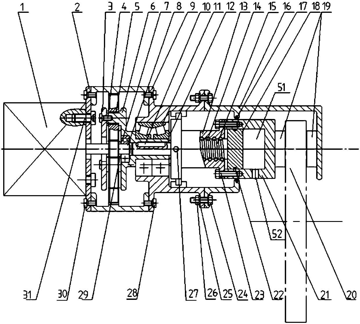
[0072] In order to further illustrate the technical scheme of the present invention and its specific working process, in conjunction with the accompanying drawings, the specific implementation of the present invention is as follows:

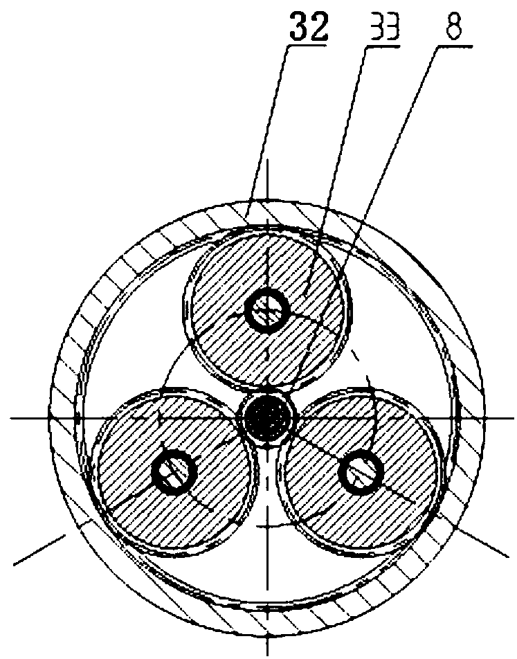
[0073] Such as figure 1 As shown, the present invention discloses an electromechanical hydraulic brake, which is composed of a motor, a planetary gear train assembly, a ball screw assembly, a brake wheel cylinder assembly, a box assembly, a friction lining and a brake disc; the motor , The planetary gear train assembly, the ball screw assembly, and the brake wheel cylinder assembly are arranged in sequence from back to front. The output shaft of the motor 1 is coaxially connected with the sun gear shaft 8 of the planetary gear train assembly. The frame is coaxially connected with the ball screw screw 15 of the ball screw assembly. The wheel brake cylinder cylinder 21 of the brake wheel cylinder assembly is fixedly connected with the ball screw nut 13...


PUM


Abstract

The invention discloses an electronic mechanical hydraulic brake, a braking control method and an electronic hydraulic brake-by-wire system. A brake wheel cylinder component is added based on a planetgearing component and ball screw pair component of an original electronic mechanical brake to form the electronic mechanical hydraulic brake herein; power output by a motor is transferred to a brakewheel cylinder block sequentially through the planet gearing component and the ball screw pair component; the brake wheel cylinder block is moved back and forth so as to arrive at pressurizing or braking removal; in addition, a hydraulic cavity of the brake wheel cylinder block is connected with an external hydraulic brake system through a normally opened electromagnetic valve; when a brake motoris powered off and fails, the normally opened electromagnetic valve can be opened so that the hydraulic cavity is connected with a brake master cylinder of a brake system, hydraulic oil is charged into the hydraulic cavity to drive the brake wheel cylinder block to move, and pressurized braking under power-off failure is achieved. The motor driven braking mode and the brake wheel cylinder hydraulic braking mode are employed herein, braking by wire is achieved, and braking of the brake system under failure can also be achieved.

Description

Technical field [0001] The invention belongs to the technical field of automobile brake by wire, and specifically relates to an electronic mechanical hydraulic brake, a brake control method and an electronic hydraulic brake by wire system. Background technique [0002] With the current development of energy-saving and new energy vehicle technologies, people have put forward higher requirements for the integration and electrification of vehicles. At present, most fuel vehicles and some new energy vehicles still use traditional braking systems. The traditional braking system uses vacuum boosters, pump motors, accumulator pumps, etc., and at the same time has certain complexity in the layout of hydraulic pipelines. Therefore, for energy-saving and new energy vehicles, it adopts a higher degree of integration and electrification. Better security by-wire system is its development trend. [0003] At present, the wire-controlled hydraulic brake system and the wire-controlled electronic ...

Claims


Application Information

Patent Timeline
Patent Type & Authority Applications(China)
IPC IPC(8): B60T13/66B60T13/68B60T13/74
CPCB60T13/662B60T13/686B60T13/745
Inventor 李静张振兆王春迪
Owner JILIN UNIV
Why Eureka
Try Eureka