Novel drive-by-wire electric braking system

A technology of electric braking and wire control, which is applied in the direction of braking safety systems, brakes, and braking transmission devices. Compact structure, achieve the effect of brake-by-wire

Pending Publication Date: 2022-07-01
陈琳
View PDF0 Cites 0 Cited by
  • Summary
  • Abstract
  • Description
  • Claims
  • Application Information

AI Technical Summary

Problems solved by technology

The system controls the braking force and pedal force at the same time, and it is easy for the driver to feel non-linear braking, especially when high-dynamic driving and braking energy recovery are involved, and the pedal force and braking experience are not good when exiting.
Although when the electric booster fails, the brake pedal push rod 1' directly drives the lead screw 2' to move in the groove of the spline 3', and directly compresses the piston of the brake master cylinder 6', which can realize the mechanical redundancy of the brake; but when When the vehicle needs to be braked under automatic driving conditions, the motor 6' directly drives the screw 2' to move, and drives the brake pedal push rod 1' to move. The brake pedal that cannot achieve mechanical full decoupling will produce follow-up. Drivers may step on the air or push their feet, which will cause some drivers to give up and continue to step on the brake pedal, resulting in dangerous situations

Method used


Image

  • Novel drive-by-wire electric braking system
  • Novel drive-by-wire electric braking system
  • Novel drive-by-wire electric braking system

Examples


Embodiment 1

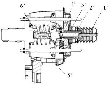
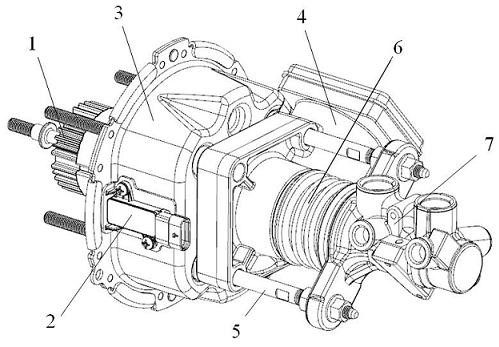
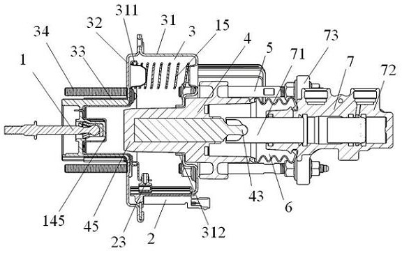
[0070] The present invention includes a pedal force transmission assembly 1, a pedal stroke sensor 2, a support housing 3, an electric push rod assembly 4, a guide rod 5, a protective cover 6, and a brake master cylinder 7; Figure 2-8 shown.

[0071] like image 3 , the support casing 3 includes a front casing 31 , a rear casing 32 , a center sleeve 33 , and a positioning bolt 34 , and the front casing 31 has a central hole 312 .

[0072] The pedal force transmission assembly 1 is installed in the center sleeve 33 of the support housing 3, and can slide axially therein; the pedal force transmission assembly 1 has a circumferentially arranged spring 15; the other end of the spring 15 supports On the inner spring seat 311 of the front housing 31 ; further, the spring 15 can be arranged at the center position of the pedal force transmission assembly 1 .

[0073] The pedal stroke sensor 2 is mounted on the support housing 3 and connected to the pedal force displacement assembly...

Embodiment 1

[0086] Based on Embodiment 1, the pedal force transmission assembly 1 includes a top rod 11 , a ball head cover 12 , a sliding sleeve 13 , a support sleeve 14 , a spring 15 , and an anti-vibration pad 16 , such as Figure 4 , Figure 5 shown.

[0087] The top rod 11 is a rod-shaped structure, the head 111 is a threaded structure or a fish-eye structure, and the tail 112 is a ball-head structure;

[0088] The sliding sleeve 13 includes an outer groove 131 , a positioning groove 132 , an undercut 133 and an inner assembly hole 134 .

[0089] Preferably, the outer groove 131 is a plurality of ribs and grooves arranged in the circumferential direction, which cooperate with the inner surface of the center sleeve 33 on the support shell 3; the cross-section of the ribs and grooves is not limited to a certain shape.

[0090] The ball head cover 12 is a hat-shaped structure, the mouth has an inverted buckle 121, the outer side is matched with the inner inverted buckle 133 of the sli...

Embodiment 3

[0101] Based on Embodiment 1, the pedal stroke sensor 2 is a linear displacement sensor, including a sensor body 21, a chute 22, a slider 23, and a positioning column 24, such as Image 6 .

[0102] The sensor body 21 can be a contact type or non-contact type, single-channel or multi-channel linear displacement sensor of any principle, such as a Hall type, an eddy current type, a sliding sheet resistance type, and the like.

[0103] The chute 22 is composed of a convex rib and a T-shaped groove, and cooperates with the convex rib on the slider 23 to prevent it from falling out when sliding, which affects the measurement accuracy.

[0104] The slider 23 may have built-in magnets or metal sheets, or built-in contacts according to the principle of the sensor.


PUM


Abstract

The invention discloses a novel drive-by-wire electric brake system which comprises a pedal force transmission assembly, a pedal travel sensor, a supporting shell, an electric push rod assembly, a guide rod, a protective cover and a brake master cylinder. The pedal force transmission assembly is connected with the brake pedal and the pedal travel sensor. The supporting shell comprises a front shell body and a rear shell body, the pedal force transmission assembly is assembled in the two shell bodies, and the pedal travel sensor and the guide rod are assembled on the front shell body. The electric push rod assembly comprises a controller, a motor and a speed reduction transmission mechanism, a guide rod hole is formed in a shell of the electric push rod assembly and matched with a guide rod fixed to the supporting shell, and the electric push rod assembly can slide along the guide rod. The other end of the guide rod is fixedly connected with a mounting hole of the brake master cylinder. The brake master cylinder and the electric push rod assembly are sealed through a protective cover. Compared with an existing brake-by-wire system, the full-decoupling brake-by-wire system is compact in size, safe and reliable in mechanical structure and capable of achieving full-decoupling brake-by-wire while meeting the relevant national standard of a passenger car brake system.

Description

technical field [0001] The present invention relates to an automobile braking system, in particular to electric braking and brake-by-wire. Background technique [0002] At present, due to the gradual popularization of new energy vehicles, the brake vacuum booster will gradually be electrified. At the same time, due to the requirements of automatic driving and intelligent active braking, the braking system needs a system that can realize wire control and meet the requirements of full mechanical decoupling between the pedal and the booster during automatic driving. Redundant mechanical brakes can be provided to ensure vehicle safety. [0003] The current wire-controlled electric braking system is generally composed of a pedal ejector, a controller, a motor, a push rod mechanism, a brake master cylinder, etc. The push rod mechanism is generally composed of a multi-stage gear reduction mechanism and a screw screw. The worm gear structure and the rack and pinion mechanism both ...

Claims


Application Information

Patent Timeline
Patent Type & Authority Applications(China)
IPC IPC(8): B60T13/74B60T17/18
CPCB60T13/745B60T17/18
Inventor 不公告发明人
Owner 陈琳
Why Eureka
Try Eureka