
Adjusting mechanism of road bicycle

An adjustment mechanism and bicycle technology, which is applied to bicycle accessories, bicycle auxiliary equipment, steering mechanisms, etc., can solve the problems that the position of the bicycle faucet is not easy to adjust and use, and achieve the effect of easy installation and disassembly, easy operation, and simple adjustment process

Inactive Publication Date: 2020-04-07
杭州万旭机械有限公司
View PDF0 Cites 0 Cited by
  • Summary
  • Abstract
  • Description
  • Claims
  • Application Information

AI Technical Summary

Problems solved by technology

[0003] The purpose of the present invention is to provide an adjustment mechanism for road bicycles to solve the problem that the position of the bicycle faucet is not easy to adjust during the use of the existing road bicycle proposed in the above background technology, and most users can only adjust the height of the seat cushion to adapt to the bicycle faucet. , there is a problem that it is not easy to use

Method used


Image

  • Adjusting mechanism of road bicycle
  • Adjusting mechanism of road bicycle
  • Adjusting mechanism of road bicycle

Examples


Embodiment 1

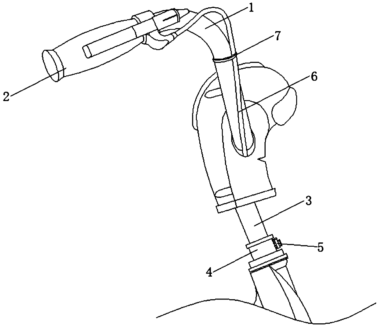
[0020] see Figure 1-2 The present invention provides a technical solution: the adjustment mechanism of a road bicycle includes a bicycle faucet 1, a handle main body 2 is installed at one end of the bicycle faucet 1, a movable column 3 is connected to the bottom of the bicycle faucet 1, and the outer side of the movable column 3 is movably connected with a The connecting sleeve 4 is provided with a locking mechanism 5 on the outside of the connecting sleeve 4 , the brake wire 6 is connected to the outside of the handle body 2 , and the wire harness mechanism 7 is installed on the outside of the bicycle faucet 1 .

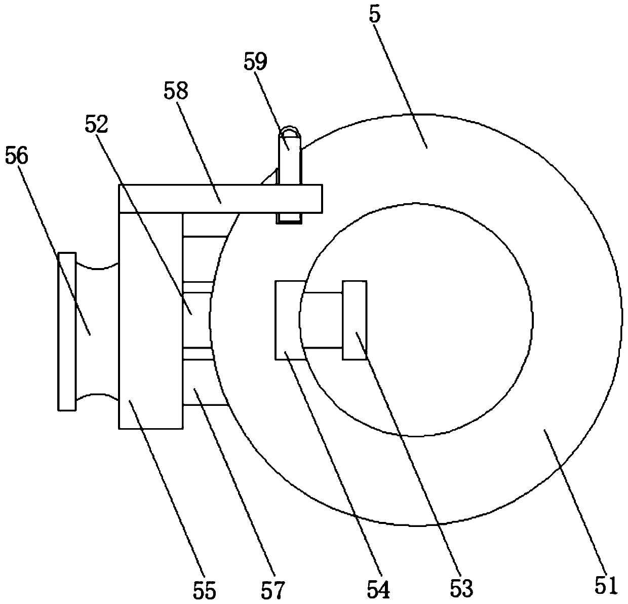
[0021] In this embodiment, preferably, the locking mechanism 5 includes a fixed sleeve 51, the inside of the fixed sleeve 51 is movably connected with a movable rod 52 extending to the outside, one end of the movable rod 52 is equipped with a fixed block 53, and the other end of the movable rod 52 Mounting plate 55 is installed, and the inside of fixed cover 51 is ...

Embodiment 2

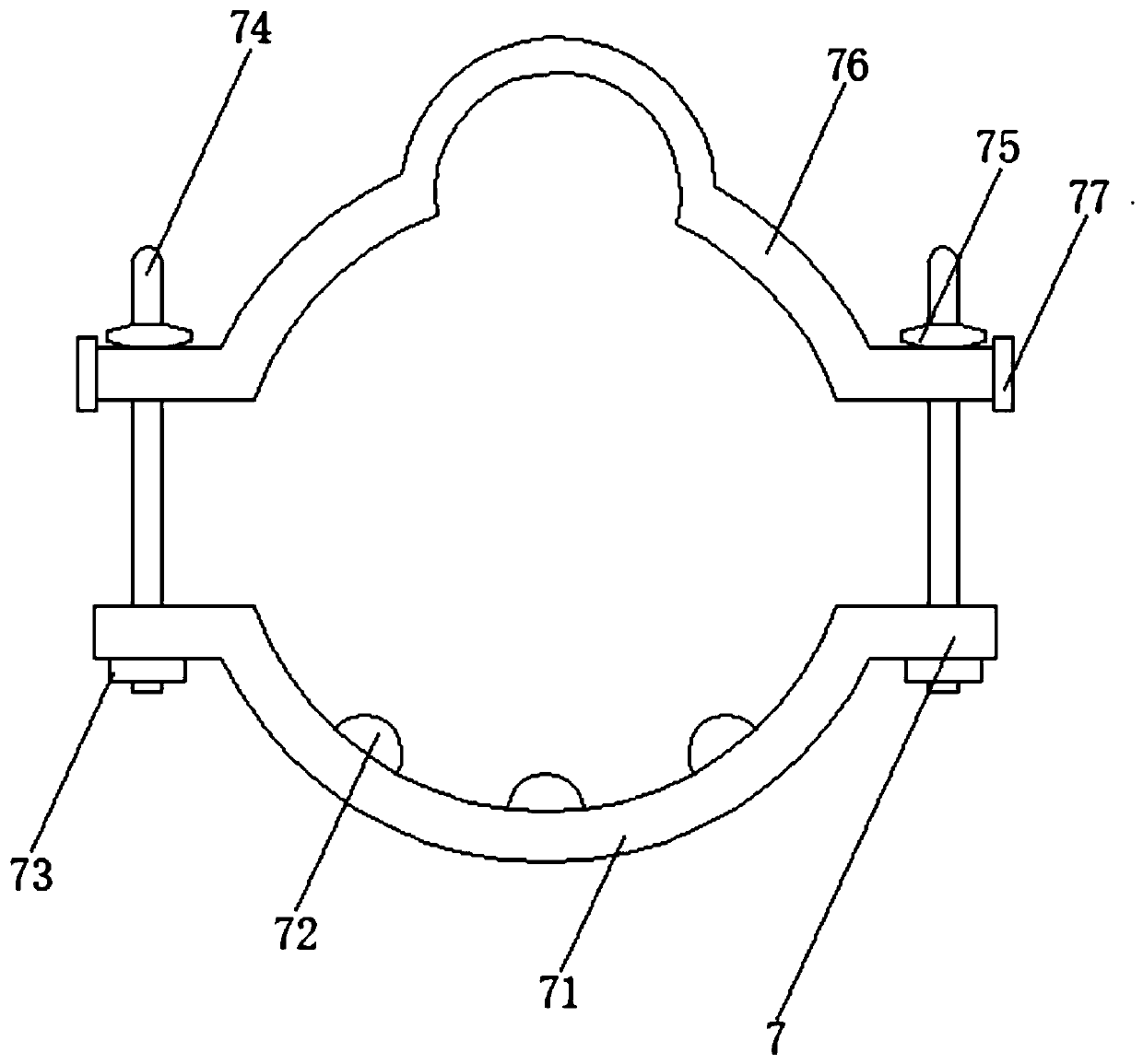
[0026] see Figure 1-3 The present invention provides a technical solution: the adjustment mechanism of a road bicycle includes a bicycle faucet 1, a handle main body 2 is installed at one end of the bicycle faucet 1, a movable column 3 is connected to the bottom of the bicycle faucet 1, and the outer side of the movable column 3 is movably connected with a The connecting sleeve 4 is provided with a locking mechanism 5 on the outside of the connecting sleeve 4 , the brake wire 6 is connected to the outside of the handle body 2 , and the wire harness mechanism 7 is installed on the outside of the bicycle faucet 1 .

[0027] In this embodiment, preferably, the locking mechanism 5 includes a fixed sleeve 51, the inside of the fixed sleeve 51 is movably connected with a movable rod 52 extending to the outside, one end of the movable rod 52 is equipped with a fixed block 53, and the other end of the movable rod 52 Mounting plate 55 is installed, and the inside of fixed cover 51 is ...


PUM


Abstract

The invention discloses an adjusting mechanism of a road bicycle. The mechanism comprises a bicycle handlebar body, a handlebar main body is installed at one end of the bicycle handlebar body, a movable column is connected to the bottom of the bicycle handlebar body, a connecting sleeve is movably connected to the outer side of the movable column, a locking mechanism is arranged on the outer sideof the connecting sleeve, and a brake cable is connected to the outer side of the handlebar main body. Through the arrangement of the locking mechanism, only the locking block needs to be pulled outwards, the handle block can be pulled outwards at the moment, the handle block drives the movable rod to move, the height of the movable column can be freely adjusted, the handle block is pushed back, and the locking block is inserted back. According to the brake cable fixing device, a brake cable can be placed at a proper position by rotating the threaded sleeve and pulling the cable bundling ringoutwards, then the cable bundling ring is sleeved back, the threaded sleeve on the outer side of the threaded rod is screwed down, the brake cable can be fixed, and mounting and dismounting are easy and convenient.

Description

technical field [0001] The invention belongs to the technical field of bicycles, and in particular relates to an adjustment mechanism of a road bicycle. Background technique [0002] When a road bicycle is used as a type of bicycle, it refers to a type of bicycle used on road surfaces (or artificially hardened roads, or gravel roads), which can be used for road bicycle competitions. In order to achieve high-speed riding, the weight of the body is lighter and the wind resistance is smaller. During the riding process, in order to facilitate the user to exert force, some parameters of the road bike need to be adjusted by the user. During the use of the existing road bike, The position of the bicycle faucet is not easy to adjust. Most users can only adjust the height of the seat cushion to adapt to the bicycle faucet. There is a problem that it is not easy to use. For this reason, we propose an adjustment mechanism for road bicycles. Contents of the invention [0003] The pur...

Claims


Application Information

Patent Timeline
Patent Type & Authority Applications(China)
IPC IPC(8): B62K21/22B62J11/10
CPCB62J99/00B62K21/22
Inventor 来坚强
Owner 杭州万旭机械有限公司
Learn More