
Electronic fly killing device

A fly-killing and electronic technology, which is applied in the fields of trapping or killing insects, applications, animal husbandry, etc., can solve the problems of fly-attracting liquid and fly-attractant that cannot be supplemented, simple, cannot be used for a long time, and efficient fly-killing.

Pending Publication Date: 2020-04-10
范玉泽
View PDF0 Cites 0 Cited by
  • Summary
  • Abstract
  • Description
  • Claims
  • Application Information

AI Technical Summary

Problems solved by technology

[0003] However, the structure of the current fly-killing equipment is too simple, and the fly-attracting liquid or fly-attracting agent used cannot be supplemented. Fly killing effect

Method used


Image

  • Electronic fly killing device
  • Electronic fly killing device
  • Electronic fly killing device

Examples


Embodiment Construction

[0019] The following specific examples illustrate the implementation of the present invention. Those familiar with this technology can easily understand the other advantages and effects of the present invention from the content disclosed in this specification. Obviously, the described embodiments are part of the embodiments of the present invention. , Not all examples. Based on the embodiments of the present invention, all other embodiments obtained by those of ordinary skill in the art without creative work shall fall within the protection scope of the present invention.

[0020] It should be noted that in the description of the present invention, the terms "in", "upper", "lower", "inner" and other terms indicating the direction or positional relationship are based on the direction or positional relationship shown in the drawings. It is only for the convenience of description, rather than indicating or implying that the device or element must have a specific orientation, be conf...


PUM


Abstract

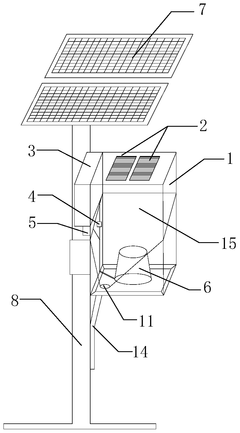
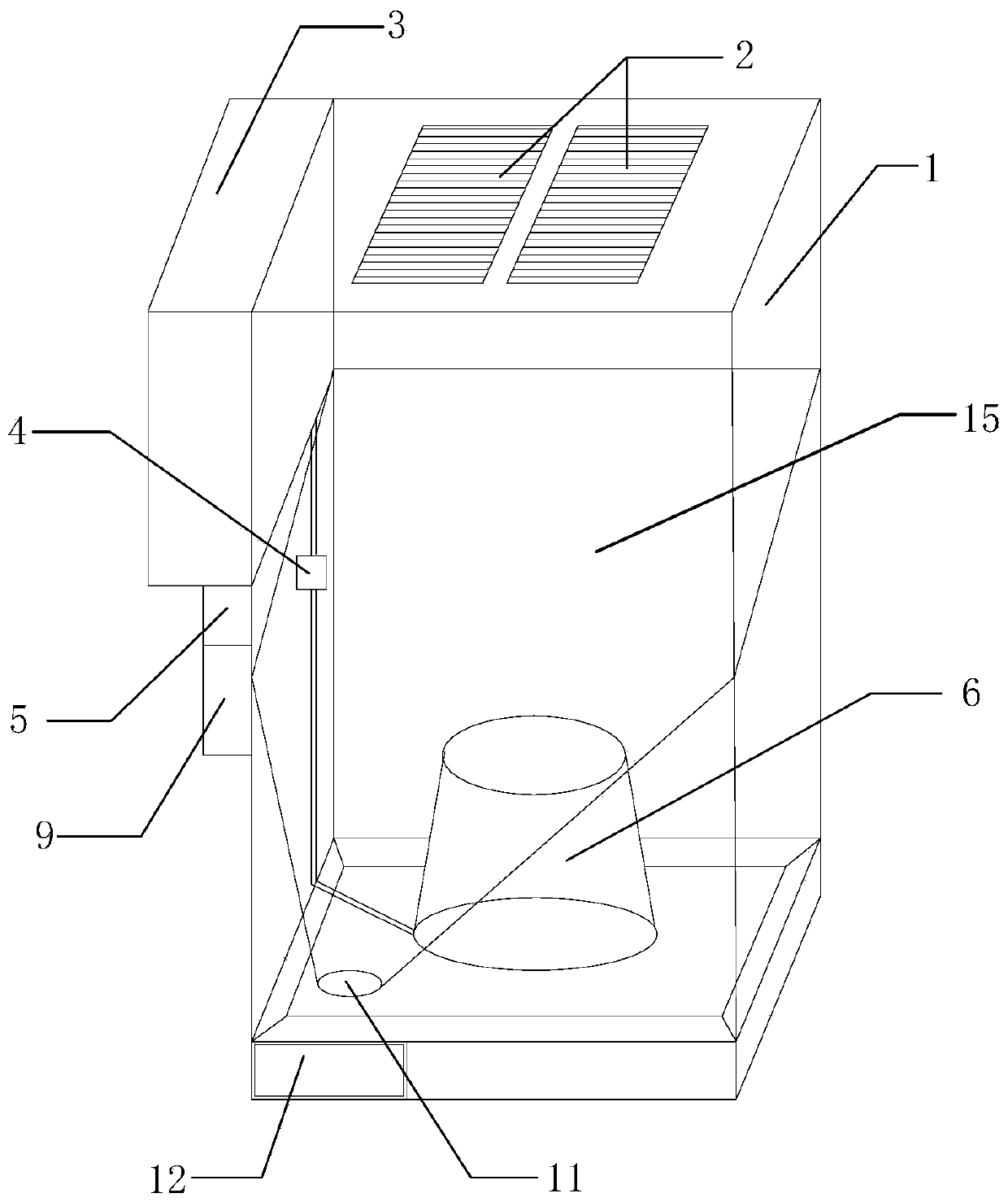
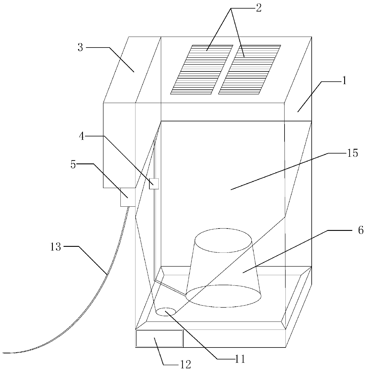
The invention belongs to the technical field of electronic fly killing device, and discloses an electronic fly killing device. The electronic fly killing device comprises a shell, electronic fly killing panels, a fly-inducing liquid water tank, a water pump, a controlling device, a power supply and a fly-inducing liquid tray, wherein the fly-inducing liquid water tank and the controlling device are arranged on the outer side wall of the shell; the fly-inducing liquid tray is arranged in the shell; a fly outlet is formed in the bottom of the shell; the bottom of the shell is provided with a smooth concave-shaped curved face; at least one electronic fly killing panel is arranged on the top of the shell; and when flies are attracted by smell of the fly-inducing liquid and fly into the shell through the bottom of a conical tube, the flies are burned or killed by burning due to high pressure of the electronic fly killing panels, and bodies of the flies directly slip into the fly outlet along the smooth curved face of the bottom. After the electronic fly killing device is connected with a solar battery panel, the electronic fly killing device can be arranged outdoors; and moreover, the electronic fly killing device also can be directly connected with an indoor power supply or a built-in battery for supplying power, and therefore, different using environments can be met.

Description

Technical field [0001] The invention relates to the technical field of electronic fly-killing equipment, in particular to an electronic fly-killing device. Background technique [0002] Flies often appear in the living environment. Bacteria spread by stopping, licking or excreting. It is an accomplice in the spread of diseases such as dysentery and cholera, and its reproduction rate is extremely fast, so flies are listed as the "four pests". With the development of science and technology, many electronic devices used to kill flies have appeared. [0003] However, the current fly-killing equipment is too simple in structure, and the fly attractant or fly attractant cannot be supplemented. The fly-killing effect slowly decreases with time, and it cannot be used for a long time and high efficiency. It is necessary to manually replace the fly attractant to ensure Anti-fly effect. [0004] Therefore, an electronic fly-killing device is needed in the art to solve the above-mentioned prob...

Claims


Application Information

Patent Timeline
IPC IPC(8): A01M1/02A01M1/22
CPCA01M1/02A01M1/223
Inventor 范玉泽范洪菩
Owner 范玉泽
Learn More