Airless engine with gas and water recycling

a technology of airless engines and gas and water, which is applied in the direction of machines/engines, mechanical equipment, and non-fuel substance addition to fuel, etc. it can solve the problems of reducing affecting the efficiency of the engine, so as to reduce the amount of unburned hydrocarbons, reduce costs, and eliminate most harmful pollutants

Inactive Publication Date: 2011-06-14
SCHECHTER MICHAEL MOSES
View PDF18 Cites 58 Cited by
  • Summary
  • Abstract
  • Description
  • Claims
  • Application Information

AI Technical Summary

Benefits of technology

[0035]One object of the present invention is to achieve a complete elimination of nitrogen oxides emissions from internal-combustion engines. This is achieved by eliminating nitrogen. Since no atmospheric air is inducted into the engine, the gas that participates in combustion contains no nitrogen. As a result, no nitrogen oxides are produced, and the engine has zero nitrogen oxides emission. This resolves one of the most insidious problems associated with internal combustion engine operation. It also leads to a very substantial reduction in costs, since it eliminates the need for the very expensive systems that are presently used to control nitrogen oxides emissions.
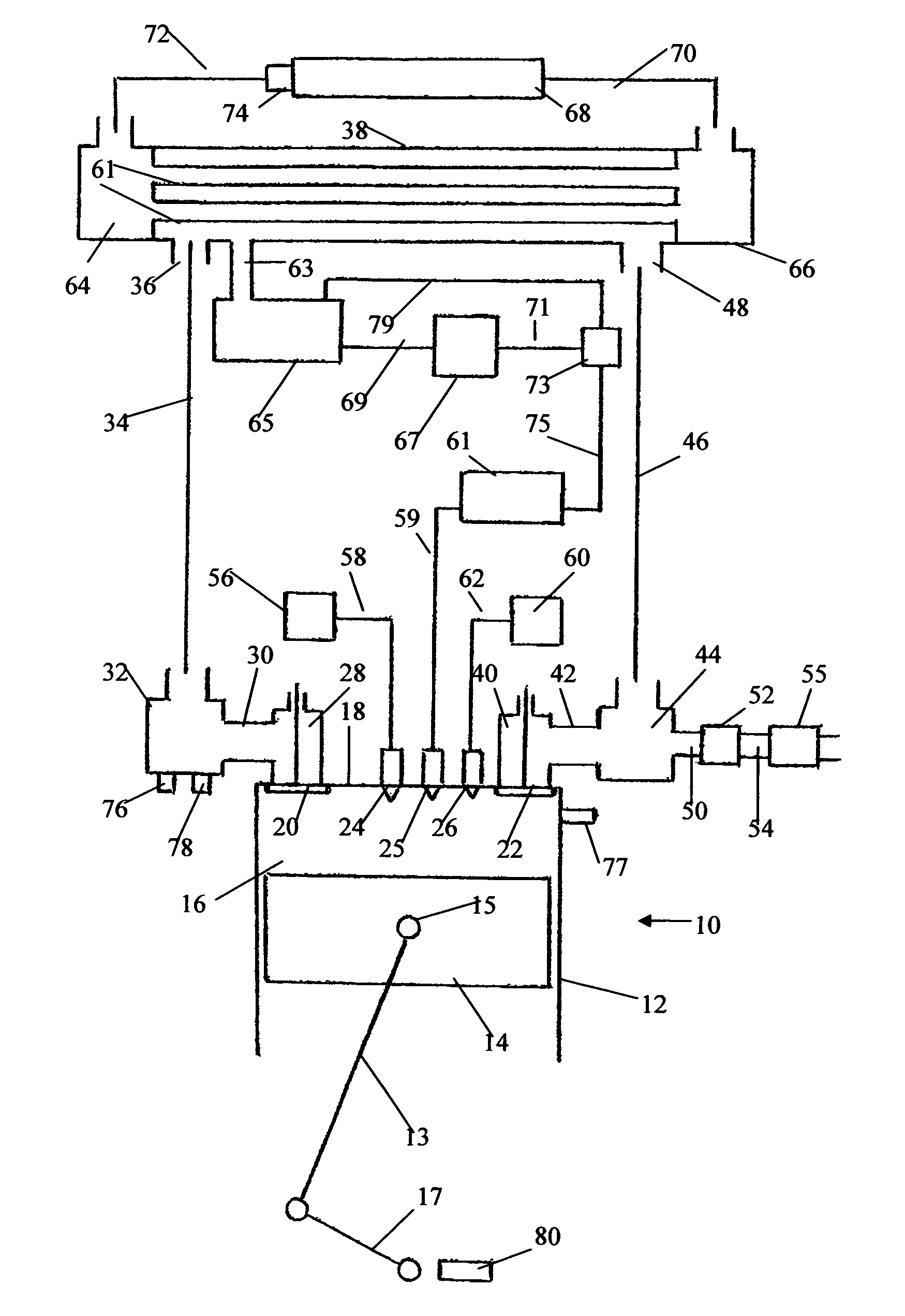
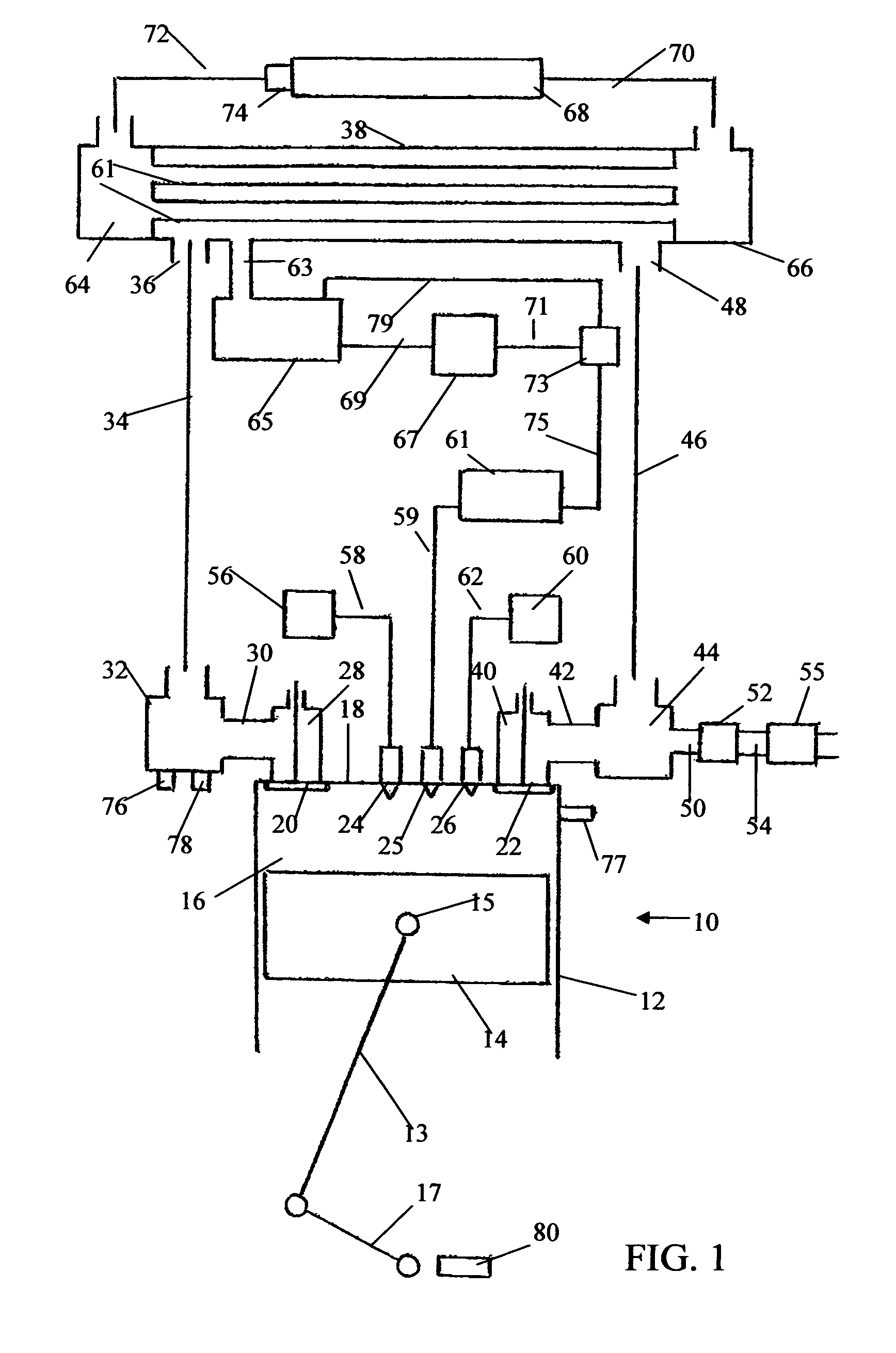
[0036]Another object of the present invention is to achieve a near-complete elimination of most harmful pollutants. In the engine of the present invention, the amount of harmful exhaust emissions, including particulate matter, unburned hydrocarbons and carbon monoxide, is greatly reduced. Most of the combustion gas expelled from each engine cylinder, after each cycle, is recycled back into the engine intake. Only a small fraction of that gas is exhausted into the exhaust pipe and, from there, into outside environment. On average, the mass of gas exhausted into the environment is equal to the mass of fuel and oxygen added to the recycled combustion gas. The percentage of combustion gas recycled back into the engine varies from 80%, at full-load, to 95% at light-load. Hence an average particle of combustion gas is recycled through the engine many times before it is exhausted into outside environment.
[0037]The recycled combustion gas caries back into the engine all the unburned hydrocarbons, particulate matter and carbon monoxide it contains. The key to reduction in those emissions is in repeatedly subjecting the same gas to the fires of combustion in the engine. Since most of the combustion gas is recycled back into the engine cylinders over-and-over again, an average particle of gas goes through the combustion process many times. In such operation, whatever did not burn the first time is repeatedly returned to the combustion chamber and is burned there. In that way, between 80 and 95% of harmful emissions produced in combustion are eliminated before they reach the engine exhaust pipe. The remaining 5 to 20% of emissions may be treated in a catalyst incorporated in the exhaust pipe. With noble metal catalyst efficiency approaching 90%, as much as 99% of harmful emissions produced in the combustion chambers can be eliminated. Also, a much smaller catalytic converter and much less noble metal are needed. This is a substantial reduction in costs.
[0038]A further object of the present invention is to achieve a substantial reduction in fuel consumption. This is achieved by condensing water vapor contained in the recycled combustion gas and adding reclaimed liquid water to that gas for evaporation at selected points in the engine cycle. Evaporation of water during gas-compression stroke absorbs the heat of compression and provides for near-isothermal compression process, which leads to a substantial reduction in the amount of work needed to compress the gas. Water injection into the engine cylinders, during the power stroke, contributes to an increase in the gas-expansion work. Inside the combustion chamber, water converts into steam that expands and performs expansion work that supplements work performed by the combustion gas. Reducing the compression work and increasing the expansion work improves the engine fuel economy.
[0039]Yet another object of the present invention is to achieve a very substantial reduction in engine size. The engine of the present invention can be considerably smaller than a conventional air-breathing engine with the same power capacity. This is because carbon dioxide, which is the main ingredient in the recycled combustion gas of the airless engine, is much heavier than nitrogen, which is the main ingredient in the intake air of a conventional air-breathing engine. Therefore, a smaller engine cylinder can receive the same mass of gas as a larger cylinder in a conventional engine using air at the same pressure and temperature. Direct injection of oxygen, fuel and water into the engine cylinder, after the intake valve closure, contributes to further reduction in engine size, since the cylinder becomes completely filled with recycled gas before oxygen, fuel and water are added. This increases the total mass of gas participating in combustion and permits a reduction in the size of the cylinder. The engine of the present invention can be about twice smaller than a conventional engine of comparable power. Such reduction in engine size is especially valuable in transportation vehicles, where it offers the advantage of lower weight and better packaging.
[0040]Still another object of the present invention is to reduce the amount of work needed to overcome the engine friction. Work of friction in internal-combustion engine is approximately proportional to the engine size. For reasons listed above, the engine of the present invention can be substantially smaller than a conventional air-breathing engine. A smaller engine has much less friction and hence a much better fuel economy.

Problems solved by technology

EGR cannot eliminate the nitrogen oxide emission, but it can reduce it.
Operating an engine with a mixture of fuel and oxygen presents some technical difficulties.
As a result, the temperature (and the pressure) would be several times higher and would reach levels that are completely unacceptable from the point of view of the engine integrity and durability.
The main disadvantage of this is that, to produce the needed amount of oxygen, the system of the above patent must handle more than four times greater amount of air than does a conventional engine that uses air directly for combustion.
Regardless of the answer to that question, the system of the above patent does not eliminate the nitrogen oxide emission, because it does not eliminate nitrogen.
Reduction in unburned hydrocarbons is possible, but it is more questionable.
It is, however, a fact that water injection into the engine cylinders did not find broad application in spite of its promise of better fuel economy.
That is because most existing internal-combustion engine are used in light transportation vehicles, such as automobiles, where there is no ready access to an outside source of water supply, and all the water needed for engine operation must be carried on-board.
Most vehicle designers are not willing to accept such deficiency in weight and packaging.
Unfortunately, the quantity of water that can be extracted from the exhaust gas of a conventional engine that uses air for its operation is too small to achieve a meaningful improvement in fuel economy.
These are very small numbers that do not justify the cost of a water vapor condensing system.
This is a heavy burden, especially if the engine is installed in a transportation vehicle.
None of the engines in the above reviewed patents is capable of self-supercharging.
Another drawback of internal-combustion engines is unburned hydrocarbon and particulate matter emission, and this is greatly reduced too.
There is less pressure blowdown at the end of the expansion stroke and more gas cooling is required, but the net result is a greater mass of gas flowing into cylinder chambers.

Method used


Image

  • Airless engine with gas and water recycling
  • Airless engine with gas and water recycling
  • Airless engine with gas and water recycling

Examples


Embodiment Construction

[0060]The method of the present invention can be applied both to four-stroke and to two-stroke engines. Both spark-ignition and compression ignition engines can be used.

1. Four-Stroke Engines

[0061]A preferred embodiment of the present invention, as applied to a four-stroke piston-type engine, is illustrated in FIGS. 1 and 2. FIG. 1 is a schematic, cross-sectional side-view of an engine cylinder and head arrangement and its connections to sources of fuel, oxygen and recycled water and to a combustion-gas cooler. An engine 10 has at least one such cylinder. A cylinder 12 contains a piston 14, which is mounted upon a connecting rod 13 by a wrist pin 15 and can reciprocate in cylinder 12, thus varying the volume of a cylinder chamber 16 enclosed between piston 14 and a cylinder head 18 attached to the top of cylinder 12. Motion of piston 14 and of connection rod 13 is transmitted to crankshaft 17.

[0062]Two types of normally-closed valves, an intake valve 20 and an exhaust valve 22, are ...


PUM


Abstract

An internal-combustion engine receives no air from outside atmosphere. Instead, combustion gas expelled from the engine is cooled and recycled back into the engine. That gas contains no nitrogen and consists mostly of carbon dioxide and water vapor. Oxygen and fuel are added to the recycled gas, and the resulting mixture is used to perform an internal-combustion cycle. Cooling that gas condenses its water vapor, and liquid water is separated from the gas. That water is used for injection into the recycled gas at a later time. A small amount of the expelled combustion gas is discharged into outside environment, and the rest is recycled. Water too is recycled back into the engine, and whatever is lost to outside environment is replaced by reclaiming water produced in combustion. No additional supply of water is needed. Since no nitrogen is present, no nitrogen oxides are produced. The amount of other harmful exhaust emissions is greatly reduced too, since most of them are recycled back into the engine. Water evaporation in the cylinders greatly improves fuel economy. The engine is inherently supercharged with combustion-gas pressure, and no turbocharger is needed. Since the combustion gas is heavier than air, the engine can be substantially smaller than a conventional engine of equal power. A smaller engine has less friction.

Description

BACKGROUND OF THE INVENTION[0001]Combustion of hydrocarbon fuels in internal-combustion engines is a major contributor to an increase in carbon dioxide content in Earth atmosphere, which according to prevailing scientific consensus contributes to global warming. It is also responsible for the ever increasing import of foreign oil, which adversely affects the national trade balance account. It is therefore imperative to achieve a substantial reduction in the amount of fuel consumed by internal-combustion engines on a national scale.[0002]Another deficiency of the internal combustion engines is in that they are prodigious producers of nitrogen oxides, unburned hydrocarbons and other air pollutants that are very harmful to human health. Efforts to control emission of those pollutants are very complex and expensive, and the results of those efforts to date are insufficient to assure clean air environment, especially in large cities.[0003]In view of the above, it is clear that it is high...

Claims


Application Information

Patent Timeline
Patent Type & Authority Patents(United States)
IPC IPC(8): F02M25/07F02B47/10F02B47/02
CPCF02M25/03F02M25/07F02M25/074F02M25/10F02M25/0727Y02T10/121F02M26/23F02M26/35Y02T10/12
Inventor SCHECHTER, MICHAEL MOSES
Owner SCHECHTER MICHAEL MOSES
Why Eureka
Try Eureka