

Computer data acquisition device and method
A data acquisition and computer technology, which is applied to the desk or table of the computer workstation, transportation and packaging, and the legs of general furniture, etc., can solve the problem of poor dustproof effect, achieve less occupied space and better dustproof effect Effect
- Summary
- Abstract
- Description
- Claims
- Application Information
AI Technical Summary
Problems solved by technology
Method used
Image

Examples
Embodiment 1
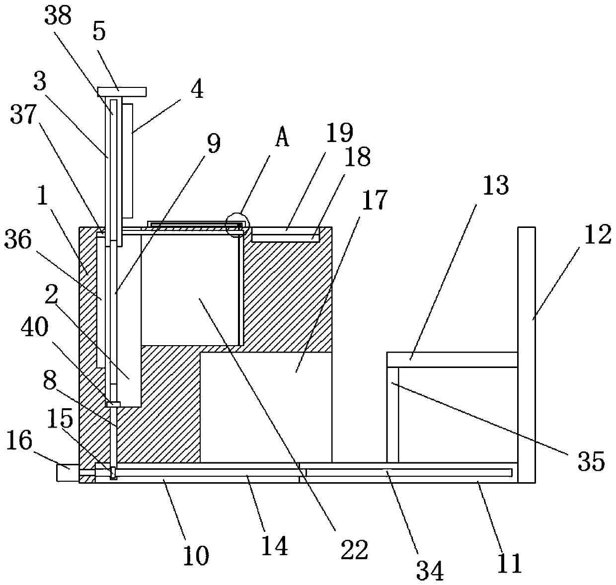
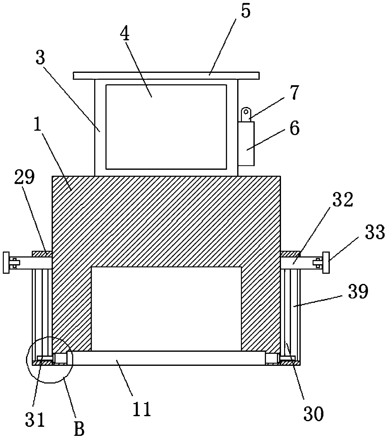
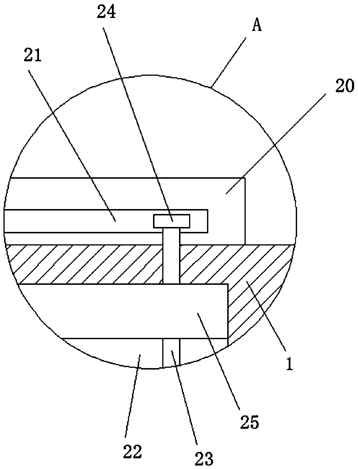
[0027] Embodiment one: refer to Figure 1-5 , a computer data acquisition device, comprising a workbench 1, a first storage tank 2 is provided on the top of the workbench 1, a mounting plate 3 is slidably installed in the first storage tank 2, and a display 4 is fixedly installed on one side of the mounting plate 3 , the outside of the mounting plate 3 is fixedly installed with a mounting base 6, the top of the mounting base 6 is equipped with a camera 7, the top of the mounting plate 3 is fixedly mounted with a cover plate 5, and the bottom inner wall of the first storage tank 2 is rotatably mounted with a worm 8, The top of the worm 8 is fixedly equipped with a first screw 9, the first screw 9 is threadedly connected with the mounting plate 3, and the bottom of one side of the workbench 1 is provided with a second storage groove 10, and a bottom plate 11 is slidably installed in the second storage groove 10. One side of the bottom plate 11 is fixedly installed with a backing...
Embodiment 2
[0036] Embodiment two: refer to Figure 1-5 , a computer data acquisition device, including a workbench 1, the top of the workbench 1 is provided with a first storage tank 2, a mounting plate 3 is slidably installed in the first storage tank 2, and one side of the mounting plate 3 is fixed by a bolt. Display 4, mounting base 6 is installed on the outside of mounting plate 3 by bolts, camera 7 is installed on the top of mounting base 6, cover plate 5 is installed on the top of mounting plate 3 by bolts, and on the bottom inner wall of first receiving groove 2 A worm 8 is installed in rotation, and the top of the worm 8 is fixed with a first screw 9 by bolts. The first screw 9 is threadedly connected with the mounting plate 3. The bottom of one side of the workbench 1 is provided with a second storage groove 10, and the second storage groove A base plate 11 is slidably installed in 10, and one side of the base plate 11 is fixed with a backing plate 12 by bolts, one side of the b...
PUM
 Abstract
Description
Claims
Application Information