
Two-way stirring equipment for chemical processing raw materials

A technology of chemical processing and raw materials, applied in chemical instruments and methods, chemical/physical processes, mixers with rotating stirring devices, etc., can solve problems affecting work efficiency, varying degrees of thickness, and easy dripping of raw materials to the outside, etc. , to achieve the effect of reducing processing steps, improving work efficiency, reducing adhesion and upper cover

Inactive Publication Date: 2020-04-10
郑志恩
View PDF0 Cites 0 Cited by
  • Summary
  • Abstract
  • Description
  • Claims
  • Application Information

AI Technical Summary

Problems solved by technology

[0005] Aiming at the deficiencies of the existing technology, the object of the present invention is to provide a two-way mixing equipment for chemical processing raw materials to solve the problems in the prior art due to the variety of chemical raw materials and the different thicknesses used in processing and application. When the consistency is low, the chemical raw materials are easy to be thrown out during the stirring process, and stick to the cover of the equipment, so that after pouring out the raw materials, when the lid is opened and the raw materials to be stirred are added, the remaining raw materials on the lid are easy to drip to the outside, thereby increasing the processing steps and affecting the work efficiency

Method used


Image

  • Two-way stirring equipment for chemical processing raw materials
  • Two-way stirring equipment for chemical processing raw materials
  • Two-way stirring equipment for chemical processing raw materials

Examples


specific Embodiment

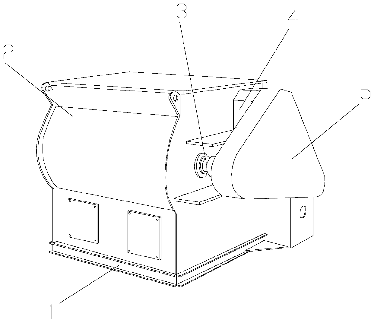
[0028] see Figure 1-Figure 11 , the specific embodiments of the present invention are as follows:

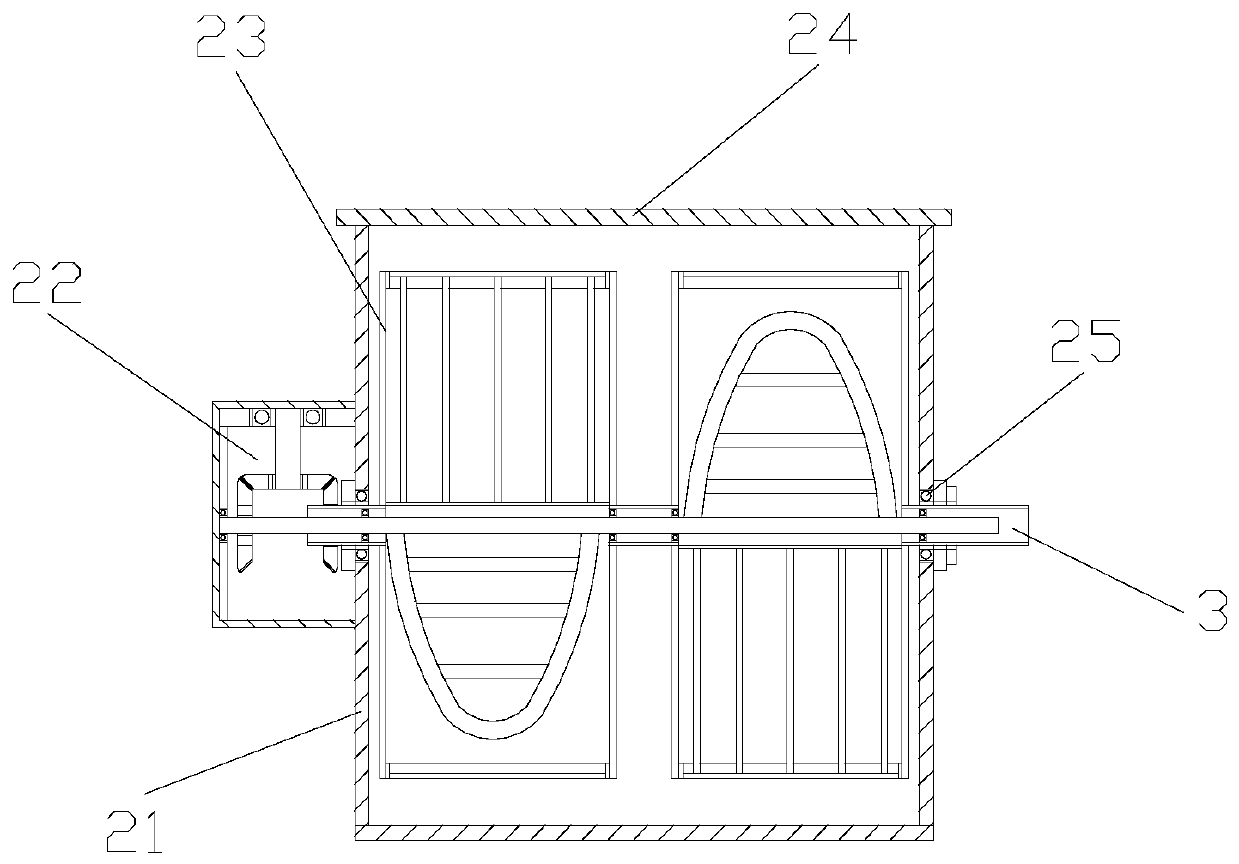
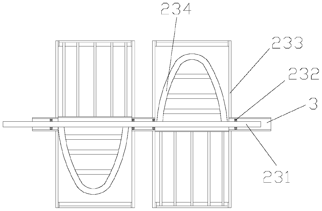
[0029] Its structure includes a base 1, a mixing structure 2, a drive shaft 3, a transmission box 4, and a driving box 5. The mixing structure 2 is horizontally installed on the upper end of the base 1 and welded to each other. There are two Outlet, the drive shaft 3 runs through the right side of the mixing structure 2 and is embedded and installed inside. The drive box 5 is installed on the right side surface of the mixing structure 2 and is mechanically connected. The drive box 5 passes through the transmission box 4 is connected with the drive shaft 3; the mixing structure 2 includes a mixing box 21, a transmission box 22, a mixing structure 23, an upper cover 24, and an outer bearing 25, and the driving shaft 3 runs through the inside of the mixing box 21 and An outer bearing 25 is installed between them. The transmission box 22 is installed on the left side of the mixing...


PUM


Abstract

The invention discloses two-way stirring equipment for chemical processing raw materials. The two-way stirring equipment structurally comprises a base, a stirring structure, a driving shaft, a transmission box and a driving box. The stirring structure is horizontally mounted at the upper end of the base; the driving shaft penetrates through the right side of the stirring structure; the driving boxis mounted on the right surface of the stirring structure; the driving box is connected with the driving shaft through the transmission box; the stirring structure comprises a stirring box, a transmission box, a stirring structure, an upper cover and an outer bearing; the driving shaft penetrates through the inner side of the stirring box and an outer bearing is mounted between the driving shaftand the inner side of the stirring box; the transmission box is mounted on the left side of the mixing box; the driving shaft is embedded into the inner side of the transmission box; the stirring structure is mounted on the outer side of the driving shaft and the left end of the stirring structure is embedded into the inner side of the transmission box; and the upper cover is horizontally arrangedabove the stirring box and movably connected. The stirring structure is arranged on the inner side of the stirring box so that chemical raw materials are prevented from being thrown out easily in thestirring process, attachment of the chemical raw materials to the upper cover is reduced, the chemical raw materials do not need to be cleaned, the processing steps are reduced and the working efficiency is improved.

Description

technical field [0001] The invention belongs to the field of chemical processing, and in particular relates to a two-way mixing equipment for chemical processing raw materials. Background technique [0002] Chemical processing is the use of chemical products to mix, or the use of chemical methods to convert products into chemical products, and in these chemical processing, it is necessary to mix and stir the raw materials to achieve mutual dispersion and mixing of raw materials and speed up the reaction. Speed, so it is necessary to use two-way mixing equipment for chemical processing raw materials to carry out a more sufficient stirring reaction for chemical raw materials, but the existing technology has the following shortcomings: [0003] Due to the variety of chemical raw materials and the different thicknesses used in processing and application, when the thickness is low, the chemical raw materials are easily thrown out during the stirring process and stick to the cover...

Claims


Application Information

Patent Timeline
Patent Type & Authority Applications(China)
IPC IPC(8): B01F7/02
CPCB01F27/192B01F27/60B01F2101/2204
Inventor 郑志恩
Owner 郑志恩
Learn More