Riveting press with automatic feeding function

An automatic feeding and riveting machine technology, which is applied in the field of riveting machines, can solve the problems of slow feeding speed, crushed products, and inability to guarantee directionality, etc., and achieve the effect of preventing throwing out or deviating from the working position, and tight connection

Pending Publication Date: 2018-04-13
史广材
View PDF6 Cites 9 Cited by
  • Summary
  • Abstract
  • Description
  • Claims
  • Application Information

AI Technical Summary

Problems solved by technology

It mainly has the following disadvantages: 1. Slow feeding speed
Because its principle adopts the suction upper mold to absorb parts (such as nut posts or screws or rivets) on the fixed plate during the downward pressing process, and does not stop during the process. If the speed is fast, the nuts on the plate will be pulled If the column (or screw or rivet) is knocked off, it cannot be sucked, resulting in invalid riveting or even crushing the product. Therefore, the pressing speed is strictly limited, and it is generally used on hydraulic presses with relatively slow speeds, and for customers who require high efficiency. can not satisfy
2. High failure rate and poor practicability
The transmission channel of the parts is made of plastic pipes. Due to this reason, many parts cannot be used. If the length of the parts is smaller than the diameter of the plastic pipe, the directionality cannot be guaranteed. Fault, if the staff does not find it in time after somersaulting, the product will be crushed; but if the length of the part is long, the nail will appear due to the bending of the plastic transmission pipe; if there is a burr on the part, it will also be stuck in the plastic In the transmission channel, it cannot be used normally
And troubleshooting is complicated: the system adopts PLC control and fully concealed installation, and the structure is complex. Once a fault occurs, it can only wait for the supplier to repair it, which seriously affects the customer's production
That is to say, in view of the above reasons, most of the customers who don't know the truth after purchasing are mostly in an idle state, unable to achieve the expected purpose, and at the same time cause waste to the economy

Method used


Image

  • Riveting press with automatic feeding function
  • Riveting press with automatic feeding function
  • Riveting press with automatic feeding function

Examples


Embodiment 1

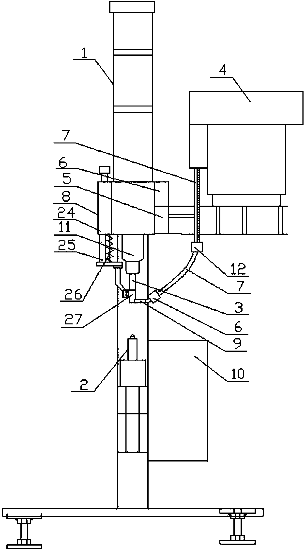
[0037] Such as Figure 1~5 As shown, an automatic feeding riveting machine includes a body 1, a vibrating plate 4, a feeding track controller 5, a feeding track 7, a lower die 2, an upper die that can move up and down along the body 1, and a clamp for clamping the upper die The auxiliary clamping mechanism 8, the auxiliary clamping mechanism 8, the vibrating plate 4 and the feeding track controller 5 are all installed on the body 1, the upper mold is slidably connected with the body 1, and the lower mold 2 is fixedly installed on the workbench of the body 1 and located at Directly below the upper die, the discharge port of the vibrating plate 4 communicates with the feed end of the feeding track 7, and the feeding track controller 5 is provided with a driving mechanism connected to the feeding track 7, and the feeding track controller 5 is connected to the driving mechanism electronically. Connected, the driving mechanism drives the feeding track 7 to approach or stay away from ...

Embodiment 2

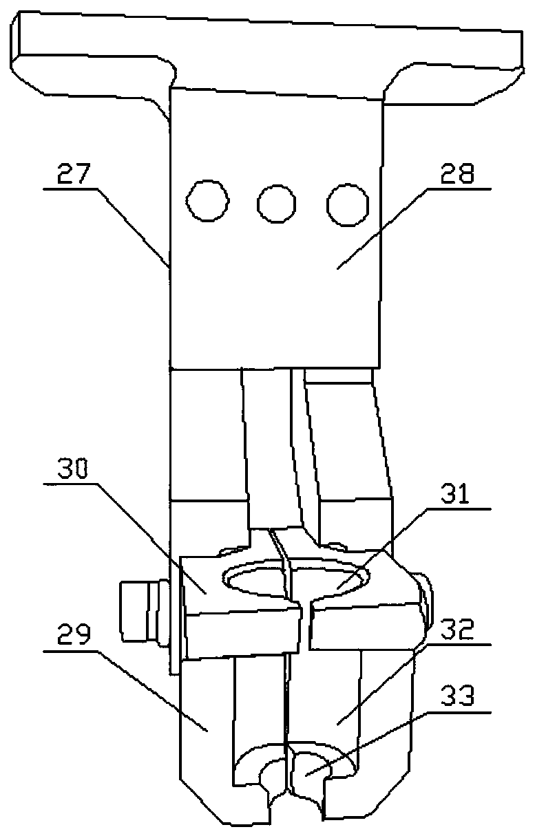
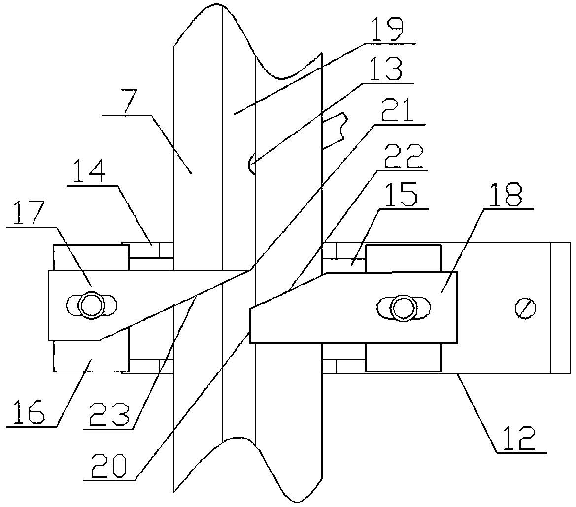
[0049] Such as Figure 1-7 As shown, the difference between embodiment 2 and embodiment 1 is that a lock door A12 is installed near the end of the vibrating plate 4 on the feeding track 7, and a lock door B38 is installed near the end of the duckbill head 9 on the feed track 7, and the lock door B38 includes Pressure cylinder 36 and push rod 37, pressure cylinder 36 is fixedly installed on the feeding track 7, the piston rod of pressure cylinder 36 is fixedly connected with push rod 37, and protrusion 35 and push rod 37 are respectively positioned at the upper and lower ends of guide groove 34, guide Both the groove 34 and the feeding groove 19 are vertically arranged with the push rod 37 . When the parts flowed to the lock door B38 through the lock door A12, the pressure cylinder 36 worked, and the parts were cut into the opening by the action of the push rod 37. There is an inclined surface C39 under the push rod 37, and the distance between one end of the inclined surface ...


PUM


Abstract

The invention relates to an riveting press with an automatic feeding function. The riveting press comprises a machine body, a vibrating disc, a feeding rail controller, a feeding rail, a lower die, anupper die capable of moving up and down along the machine body and an auxiliary clamping mechanism used for clamping the upper die; the auxiliary clamping mechanism, the vibrating disc and the feeding rail controller are installed at the machine body, the upper die is in sliding connection with the machine body, and the lower die is fixedly installed on a workbench of the machine body and is located right below the upper die; the discharging port of the vibrating disc communicates with the feeding end of the feeding rail, a driving mechanism connected with the feeding rail is arranged in thefeeding rail controller, and the feeding rail controller is electrically connected with the driving mechanism; and the driving mechanism drives the feeding rail to be close to or far away from the machine body, the auxiliary clamping mechanism is in contact with the discharging end of the feeding rail, and a duckbilled head for limiting the moving direction of a part is arranged at the dischargingend of the feeding rail. According to the riveting press, the feeding speed is high, the fault rate is low, the practicability is high, the fault removal is simple, and the maintenance is easy.

Description

technical field [0001] The invention relates to a riveting machine, in particular to an automatic feeding riveting machine. Background technique [0002] At present, for the sheet metal and metal stamping industry, the biggest bottleneck is the riveting problem. The efficiency is slow and unsafe. The low efficiency not only increases the cost of the enterprise, but once a work-related injury is caused, it will be a huge price for the enterprise and the individual. Although there are some automatic feeding systems at present, there are obvious deficiencies, which are far from satisfying the real needs of customers. Take the automatic feeding represented by the American product Hager as an example, using: vacuum suction + plastic pipe + air blowing method. It mainly has the following disadvantages: 1. The feeding speed is slow. Because its principle adopts the suction upper mold to absorb parts (such as nut posts or screws or rivets) on the fixed plate during the downward pr...

Claims


Application Information

Patent Timeline
Patent Type & Authority Applications(China)
IPC IPC(8): B21J15/42B21J15/38B21J15/32
CPCB21J15/32B21J15/38B21J15/42
Inventor 史广材
Owner 史广材
Why Eureka
Try Eureka