Supercharge Your Innovation With Domain-Expert AI Agents!

Tip, tip holder and tip automatic switching device

An automatic switching and gripper technology, applied in the direction of tailstock/top, tool holder accessories, metal processing equipment, etc., can solve problems such as positioning errors, achieve accurate installation, prevent top damage, and ensure machining accuracy.

Active Publication Date: 2020-04-10
GUANGZHOU HAOZHI ELECTROMECHANICAL
View PDF18 Cites 0 Cited by
  • Summary
  • Abstract
  • Description
  • Claims
  • Application Information

AI Technical Summary

Problems solved by technology

[0005] The third purpose of the present invention is to provide an automatic tip switching device, which can solve the problem of positioning error caused by multiple clamping of the tip, and can realize automatic switching of the tip, which is conducive to improving processing efficiency and reducing labor costs

Method used


Image

  • Tip, tip holder and tip automatic switching device
  • Tip, tip holder and tip automatic switching device
  • Tip, tip holder and tip automatic switching device

Examples


Embodiment Construction

[0032] Below, the present invention will be further described in conjunction with the accompanying drawings and specific implementation methods. It should be noted that, under the premise of not conflicting, the various embodiments described below or the technical features can be combined arbitrarily to form new embodiments. .

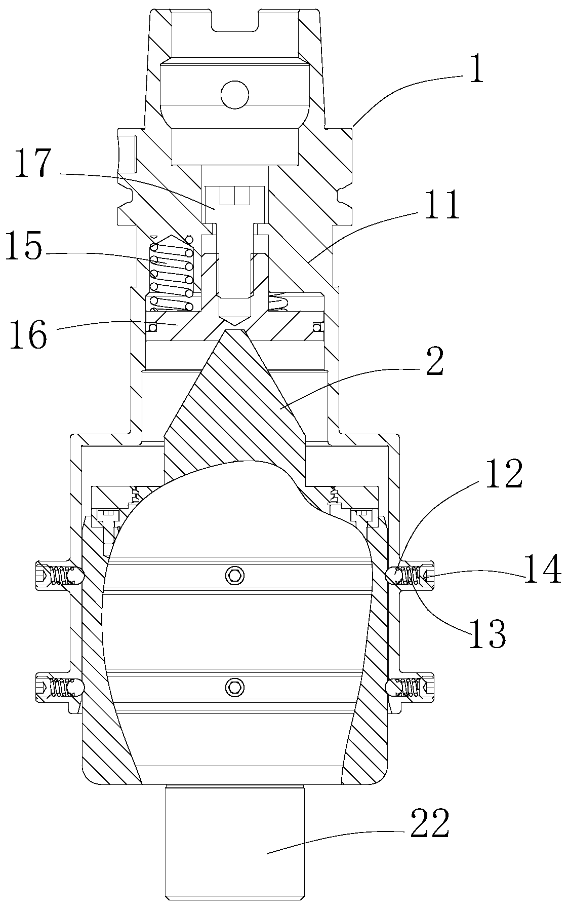
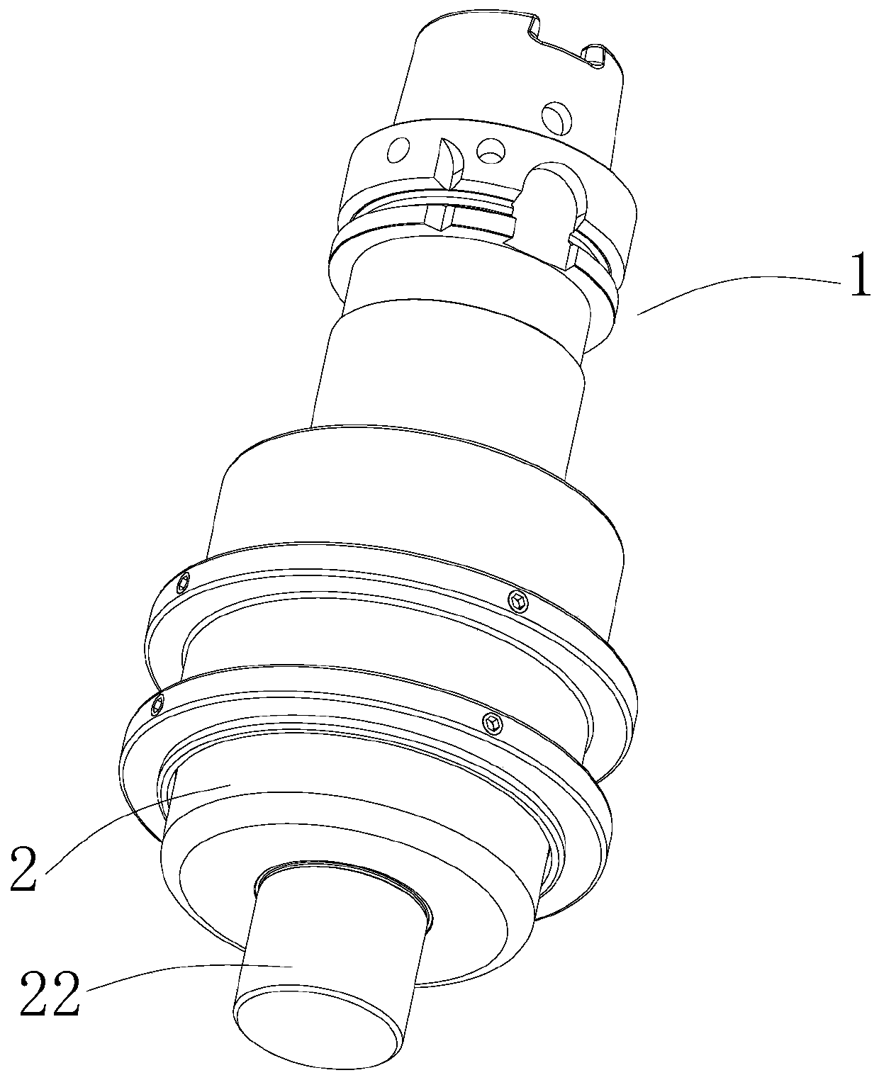
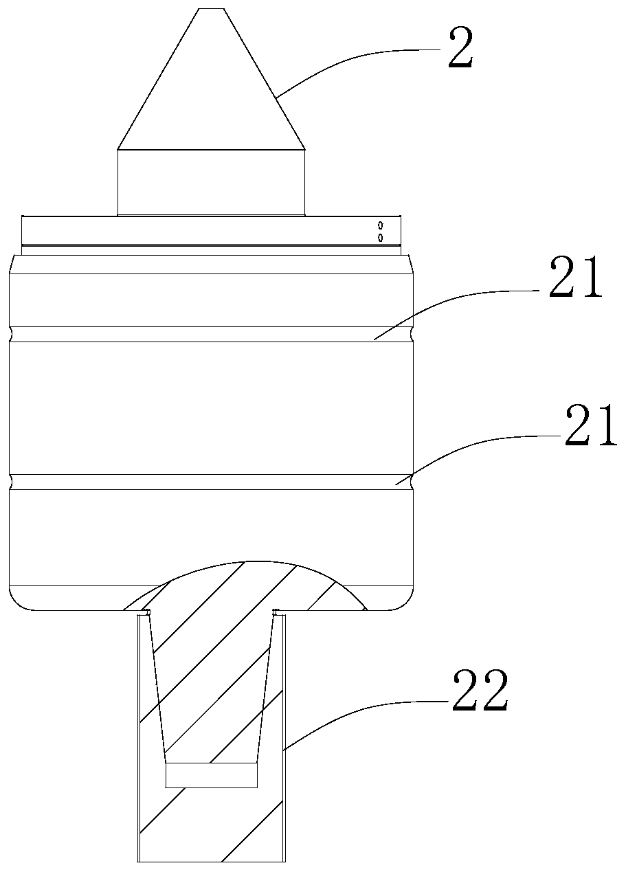
[0033] Such as Figure 1-7 As shown, the present embodiment discloses the tip 2, which includes a tip body and a connecting assembly. The surface of the tip body is provided with a positioning portion, and the connecting assembly is arranged on one end of the tip body. The connecting assembly includes several taper sleeves 22 of different diameters. Several taper sleeves 22 are socketed.

[0034] Specifically, the positioning portion is a groove arranged around the circumferential direction of the tip body. Preferably, the groove is an arc groove 21 .

[0035] More specifically, the several taper sleeves 22 are fixed by clamping.

[0036] A better ...


PUM


Abstract

The invention discloses a tip. The tip comprises a tip body and a connecting assembly, wherein a positioning part is arranged on a surface of the tip body, the connecting assembly is arranged at one end of the tip body and comprises a plurality of taper sleeves with different diameters. The invention further discloses a tip holder which comprises a clamping sleeve, a clamping mechanism and the tip, wherein the clamping sleeve is provided with a containing cavity used for bearing the tip, and the clamping mechanism is used for fixing the tip. The invention further discloses an automatic tip switching device which comprises a first lathe spindle, a second lathe spindle, a milling spindle and the tip holder, wherein a first three-jaw chuck is arranged on the first lathe spindle, a second three-jaw chuck is arranged on the second lathe spindle, the milling spindle machines a part and clamps the tip holder, and the tip can be mounted and / or dismounted on the first three-jaw chuck or the second three-jaw chuck, so two ends of the part are clamped through the tip and the first three-jaw chuck or the second three-jaw chuck correspondingly. The tip is advantaged in that the tip can be automatically switched, machining efficiency is high, and labor cost is low.

Description

technical field [0001] The invention relates to machine tool equipment, in particular to a top, a top holder and a top automatic switching device. Background technique [0002] The turning-milling compound machine tool with double lathe spindle is the latest CNC combined machine tool in the development of machine tools in the world. This machine tool can complete all the turning, drilling, and milling processes of the processed parts after one-time clamping and automatic handover, which greatly The processing efficiency of parts production is improved, and the problem of positioning error due to multiple clamping is also reduced. For the processing of some slender parts, it is necessary to use a three-jaw chuck at one end and a tip at the other end to clamp the part. However, since the top requires workers to disassemble and install frequently, the processing efficiency is greatly reduced and labor costs are wasted. In addition, the existing tip structure is relatively sim...

Claims


Application Information

Patent Timeline
Patent Type & Authority Applications(China)
IPC IPC(8): B23B23/00
CPCB23B23/005
Inventor 余辉汤秀清
Owner GUANGZHOU HAOZHI ELECTROMECHANICAL
Features
  • R&D
  • Intellectual Property
  • Life Sciences
  • Materials
  • Tech Scout
  • Unparalleled Data Quality
  • Higher Quality Content
  • 60% Fewer Hallucinations
Learn More