Groove machining device for thin plate

A bevel processing and thin plate technology, which is applied in the field of bevel processing devices for thin plate parts, can solve problems such as difficulty in controlling precision, easy deformation, and irregular shape.

Active Publication Date: 2020-04-10
HARBIN INST OF TECH +1
View PDF11 Cites 1 Cited by
  • Summary
  • Abstract
  • Description
  • Claims
  • Application Information

AI Technical Summary

Problems solved by technology

[0004] The purpose of the present invention is to solve the problem that thin-walled lightweight parts are prone to deformation and difficult to control precision due to their large size, irregular shape and low rigidity during processing, and further provide a groove for thin plate parts Processing device

Method used


Image

  • Groove machining device for thin plate
  • Groove machining device for thin plate
  • Groove machining device for thin plate

Examples


specific Embodiment approach 1

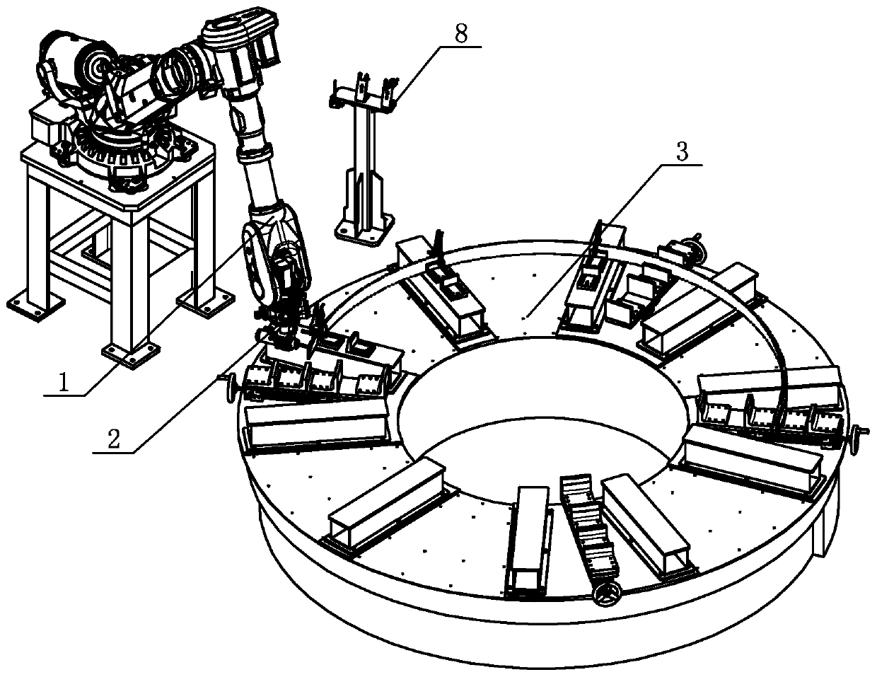
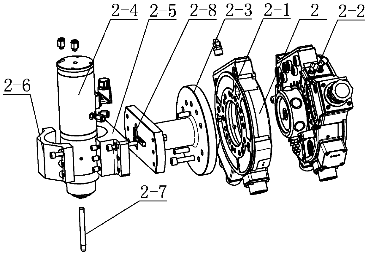
[0019] Specific implementation mode one: combine Figure 1-Figure 7 Describe this embodiment, a bevel processing device for thin plate parts described in this embodiment, it includes a mechanical arm 1, it also includes a processing mechanism 2, a clamping and fixing mechanism 3 and a tool changer assembly 8, the processing mechanism 2 Including the movable end of the quick change block 2-1, the fixed end of the quick change block 2-2, the adapter seat 2-3, the electric spindle 2-4, the electric spindle fixed seat 2-5, the compression cover plate 2-6 and the milling cutter 2-7, the output end of the mechanical arm 1 is fixedly connected to the fixed end 2-2 of the quick change block, the fixed end 2-2 of the quick change block is pneumatically locked with the movable end 2-1 of the quick change block, and the adapter seat 2-3 One end of the quick-change block is fixedly connected with the movable end 2-1, the electric spindle fixing seat 2-5 is fixedly installed on the other e...

specific Embodiment approach 2

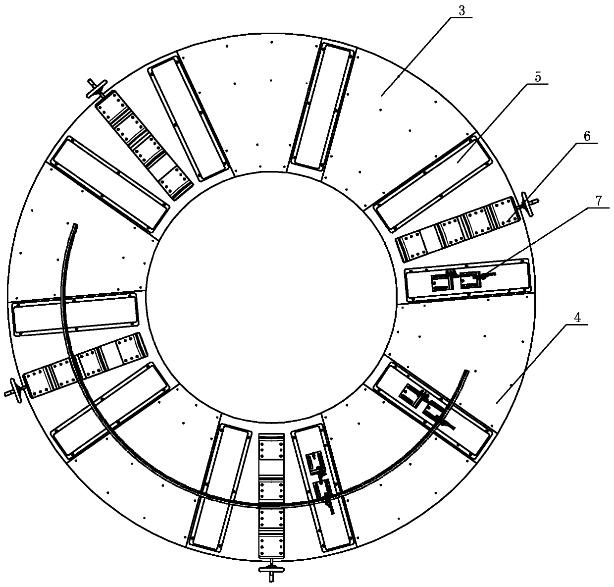
[0024] Specific implementation mode two: combination figure 1 and figure 2 Describe this embodiment, a bevel processing device for thin plate parts described in this embodiment, the clamping and fixing mechanism 3 includes a work plate 4, a plurality of support limit frames 6, a plurality of support frames 5 and multiple sets of support clips Tightening assembly 7; the work disk 4 is an annular disk body, a plurality of support frames 5 are fixedly installed on the upper end surface of the work disk 4, and a plurality of support limit frames 6 are installed on the upper end surface of the work disk 4, and each group of support clamping assemblies 7 Fixedly installed on a support frame 5, the center line of each support frame 5 along the length direction passes through the center of the work disk 4, and the center line of each support limit frame 6 passes through the center of the work disk 4 along the length direction. , in the present embodiment, the number of groups of sup...

specific Embodiment approach 3

[0025] Specific implementation mode three: combination figure 1 and figure 2 This embodiment will be described. In the bevel processing device for thin plate parts described in this embodiment, the plurality of support frames 5 are rectangular frames, and the upper surfaces of the plurality of support frames 5 are planes. The thin-walled plate workpiece is supported by the upper surface of the support frame 5 to ensure that the bottom end surface of the thin-walled plate is even and the accuracy of workpiece processing is ensured. Other methods are the same as in the second embodiment.


PUM


Abstract

The invention relates to a groove machining device for a thin plate, in particular to a groove machining device. The groove machining device for the thin plate aims to solve the problems that a thin-wall light part is easy to deform and the precision is difficult to control in a machining process due to the characteristics of large size, irregular shape and low rigidity of a thin-wall light part.The groove machining device comprises a mechanical arm, and further comprises a machining mechanism, a clamping and fixing mechanism and a knife rest changing assembly, wherein the machining mechanismcomprises a quick-change block movable end, a quick-change block fixed end, an adapter, a motorized spindle, a motorized spindle fixed base, a pressing cover plate and a milling cutter, the mechanical arm is connected with the quick-change block fixed end, the quick-change block is connected with the quick-change block movable end, the adapter is connected with the quick-change block movable end,the motorized spindle fixed base is fixedly installed at the other end of the adapter, the milling cutter is installed on the motorized spindle, the motorized spindle is installed on the motorized spindle fixed base and the pressing cover plate, the clamping and fixing mechanism is close to the mechanical arm and arranged below the machining mechanism, and the knife rest changing assembly is arranged close to the mechanical arm. The method is applied to the field of groove machining of the thin plate.

Description

technical field [0001] The invention relates to a groove processing device, in particular to a groove processing device for thin plate parts. Background technique [0002] With the rapid development of aerospace and other military industries, the requirements for dynamic characteristics, weight and reliability of products are getting higher and higher, and a large number of thin-walled and free-form surfaces are used for design. Due to their large size, irregular shape, and low rigidity, thin-walled lightweight parts are difficult to clamp, easy to deform, and difficult to control precision in the digital manufacturing process. [0003] Manufacturing in the aerospace field has the characteristics of small batches and multiple types. Traditional automated manufacturing methods cannot meet the corresponding needs. Therefore, most manufacturers currently use manual methods for manufacturing. However, with the continuous improvement of product quality and consistency requiremen...

Claims


Application Information

Patent Timeline
Patent Type & Authority Applications(China)
IPC IPC(8): B23C3/13B23Q3/06B23Q5/28
CPCB23C3/13B23Q3/062B23Q5/28
Inventor 董为高永卓杜志江李明洋董丰波窦超董吉义
Owner HARBIN INST OF TECH
Why Eureka
Try Eureka