
Steel box girder tied arch bridge structure

A technology for tied arch bridges and steel box girders, which is applied in the field of steel box girder tied arch bridges, and can solve the problems of reduced service life, inability to alleviate the vibration and impact energy of tied arch bridges, and large damage at the joints

Pending Publication Date: 2021-07-06
CCCC THIRD HIGHWAY ENG +1
View PDF11 Cites 0 Cited by
  • Summary
  • Abstract
  • Description
  • Claims
  • Application Information

AI Technical Summary

Problems solved by technology

[0004] But it still has some shortcomings. Most of the tied arch bridges will be installed on the four pre-set supporting piers during installation. It is directly connected by conventional welding or bolts, which is not convenient for fast installation of the tied arch bridge, and The function of shock absorption and impact reduction, the installation efficiency of the joint is low, and it cannot alleviate the vibration and impact energy of the tie-bar arch bridge in use, so that when the tie-bar arch bridge vibrates, the impact energy directly and completely acts on the supporting pier. The damage of the connection is relatively large, which reduces the service life. In view of this phenomenon, we propose a steel box girder tie bar arch bridge structure to solve the above problems

Method used


Image

  • Steel box girder tied arch bridge structure
  • Steel box girder tied arch bridge structure
  • Steel box girder tied arch bridge structure

Examples


Embodiment

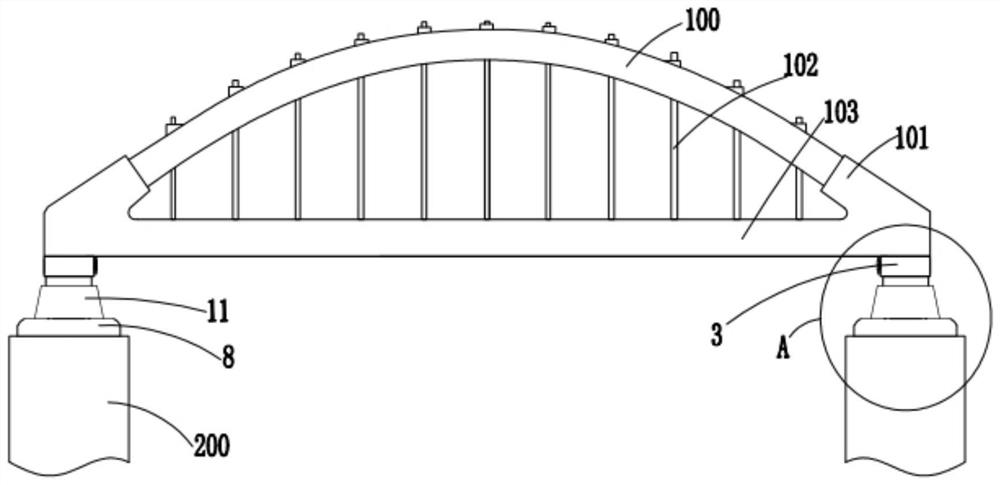
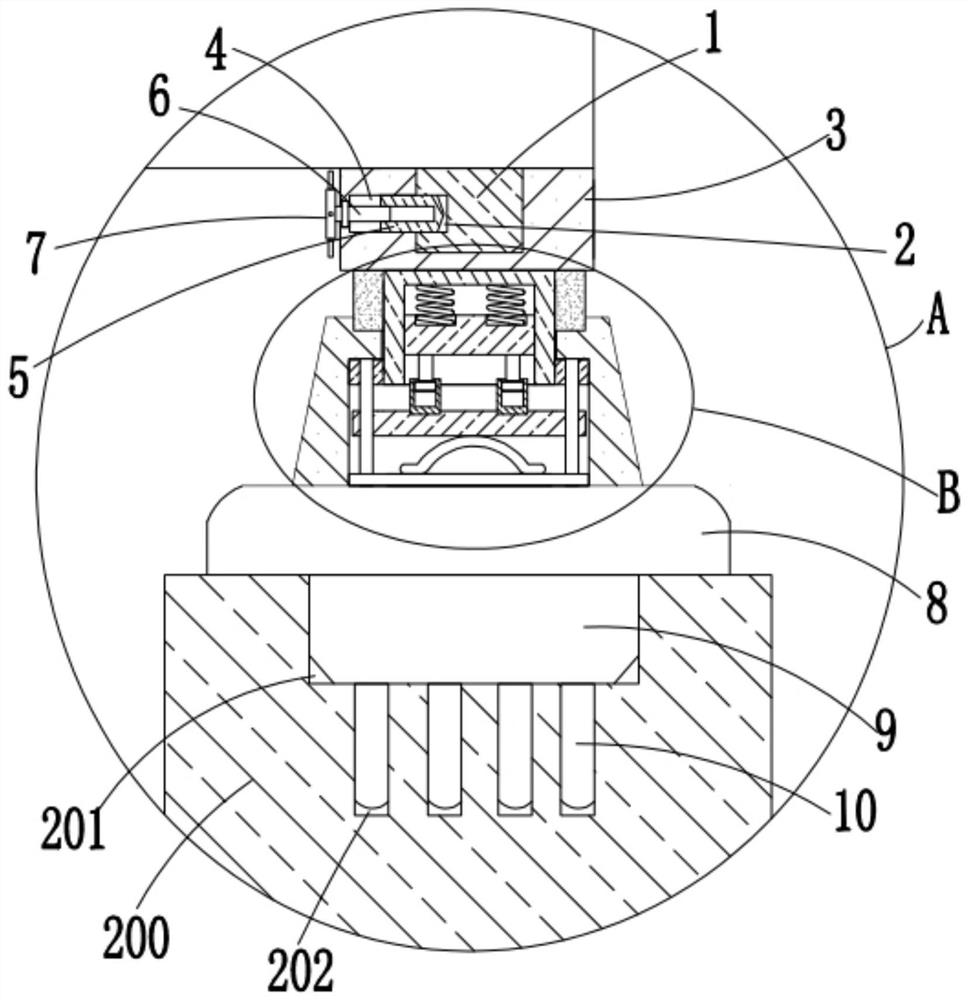
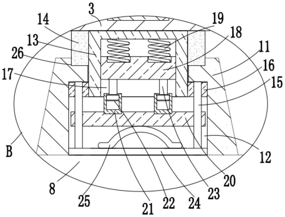
[0026] refer to Figure 1-4 , the present embodiment proposes a steel box girder tied-bar arch bridge structure, which includes an arch bridge structure body and support piers 200 respectively arranged below the four corners of the arch bridge structure body. Two arch rings 100, and a plurality of suspenders 102 arranged between the arch ring 100 and the tie beam 103, two arch feet 101 are uniformly arranged on both sides of the top of the tie beam 103, and the arch feet 101 and the corresponding arch rings The bottom end of 100 is fixedly connected, and the top of the support pier 200 is provided with a first slot 201, and the bottom inner wall of the first slot 201 is provided with a plurality of second slots 202, and the bottom four corners of the tie beam 103 are fixedly connected with Rectangular deck 1, two rectangular decks 1 opposite to each other are provided with a rectangular slot 2 on the side close to each other, and a quick-connect mechanism is arranged between t...


PUM


Abstract

The invention discloses a steel box girder tied arch bridge structure which comprises an arch bridge structure body and supporting pier bases arranged below the four corners of the arch bridge structure body respectively, and the arch bridge structure body comprises a tie beam, two arch rings arranged above the tie beam and a plurality of suspenders arranged between the arch rings and the tie beam. The two sides of the top of the tie beam are each integrally provided with two arch feet, the arch feet are fixedly connected with the bottom ends of the corresponding arch rings, first inserting grooved are formed in the tops of the supporting pier bases, and a plurality of second inserting grooves are formed in the inner walls of the bottoms of the first inserting grooves. The structure is reasonable in design, the arch bridge structure body and a quick connecting mechanism can be conveniently and quickly connected, the arch bridge structure body and the supporting pier base can be conveniently and quickly mounted through the quick connecting mechanism, the mounting efficiency is improved, the buffering, shock absorption and impact reduction of the arch bridge structure body in use are facilitated, and the risk of damage to the connecting position when the connecting position is impacted can be reduced; the service life of the connecting position is prolonged, and the use is facilitated.

Description

technical field [0001] The invention relates to the technical field of arch bridges, in particular to a steel box girder tie rod arch bridge structure. Background technique [0002] The steel box girder tied arch bridge is a bridge with a composite structure system, which is generally composed of arch rings, arch feet, suspenders, and tie beams. Its distinctive feature is that the horizontal thrust can be partially or completely borne by the tie beams; simply supported systems are often used, and the system is It is statically indeterminate on the outside and super-statically indeterminate on the inside. It has low requirements on the foundation and has a wide range of applications. This structural system is equivalent to setting a reinforced arch on a simply supported beam. Suspender, by adjusting the tension of the suspender, the stressed state of the longitudinal beam can be in the most favorable state; [0003] For this kind of steel box girder tied arch bridge structur...

Claims


Application Information

Patent Timeline
IPC IPC(8): E01D4/00E01D2/04E01D19/00
CPCE01D4/00E01D2/04E01D19/00
Inventor 乔园园袁正武于洋马耀举梁蕊刘卓谞
Owner CCCC THIRD HIGHWAY ENG
Learn More