Clutch press fitting device
A press-fit device and clutch technology, applied in metal processing, metal processing equipment, manufacturing tools, etc., can solve the problems of low clutch bolt tightening efficiency, affecting clutch assembly efficiency, and no automatic bolt tightening, etc., to improve efficiency and improve Tightening efficiency and the effect of reducing labor intensity
- Summary
- Abstract
- Description
- Claims
- Application Information
AI Technical Summary
Problems solved by technology
Method used
Image
Examples
Embodiment 1
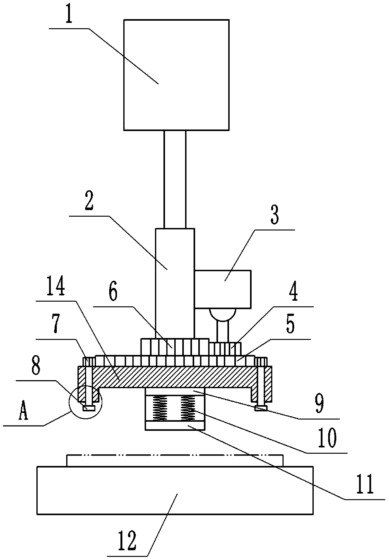
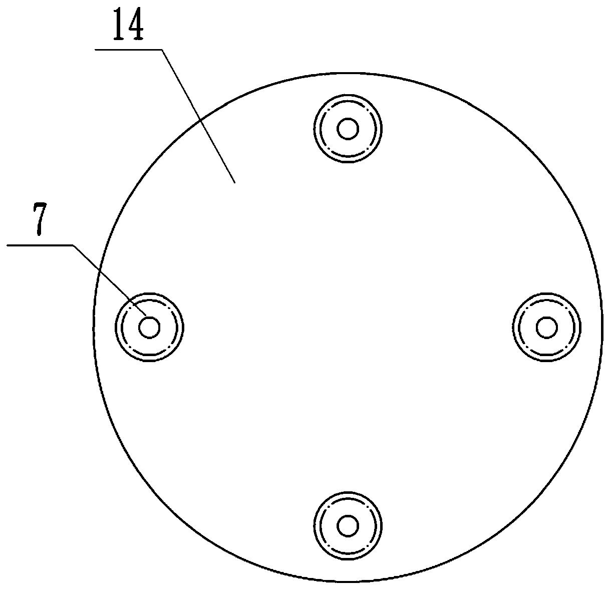
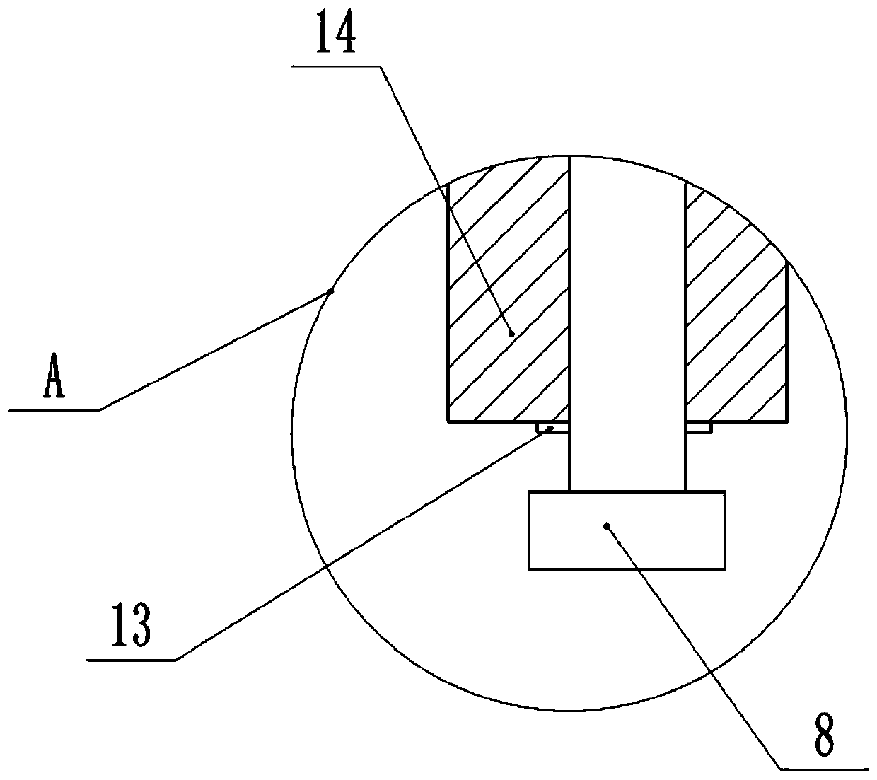
[0031] Basic as attached Figure 1-Figure 3 Shown: a clutch pressing device, including a frame, a placement table 12, a pressure head located above the placement table 12, and a hydraulic cylinder 1 for driving the pressure head to move vertically, and the placement table 12 is welded on the frame horizontally , The top of the placement table 12 is provided with a placement groove, so as to place the clutch to be pressed. The hydraulic cylinder 1 is fixed on the frame by screws, and the bottom end of the hydraulic rod of the hydraulic cylinder 1 is welded with a vertical fixed cylinder 2, and the fixed cylinder 2 is connected with the first gear 5 and the second gear 6 through bearing rotation. A gear 5 is located below the second gear 6, and the second gear 6 and the first gear 5 are welded together. A motor 3 is fixed on the right side of the fixed cylinder 2 by screws, and a driving gear 4 is welded on the output shaft of the motor 3, and the driving gear 4 meshes with the...
Embodiment 2
[0035] combine Figure 4 and Figure 5 As shown, the present embodiment also includes four bolt boxes 19 and four cylinders 15 for driving the bolt boxes 19 to move laterally. The bolt boxes 19 are in the shape of a cuboid, and the four bolt boxes 19 are evenly distributed on the outside of the fixed disk 14. Four bolt boxes 19 are radially distributed, and the bolt box 19 is located between the fixed plate 14 and the placement table 12 in the vertical direction, and the bolt box 19 is located on the outside of the fixed plate 14 in the transverse direction, and four supports are welded on the frame Block 16, four bolt boxes 19 are laterally slidably connected on the corresponding support block 16 through the cooperation of protrusions and slide grooves, the cylinder 15 is fixed on the frame by screws, and the cylinder rod of the cylinder 15 is welded on the bolt box 19 away from On one end of the fixed disk 14. In this embodiment, the end of the bolt box 19 close to the fix...
Embodiment 3
[0040] combine Figure 6-Figure 10 As shown, since the four bolt boxes 19 have the same structure, with Figure 6 Take the bolt box 19 on the left as an example, combined with Figure 8 As shown, the right end of the bolt box 19 is horizontally slidably connected with a push rod 20. Specifically, the push rod 20 is Z-shaped, and the right end of the bolt box 19 is provided with a hole, and the right end of the push rod 20 is positioned in the hole. The bottom of the bolt box 19 is provided with an accommodating groove, the bottom of the bolt box 19 is provided with a rod hole 24, the push rod 20 passes through the rod hole 24, the bottom of the push rod 20 is located in the accommodating groove, and the left end of the push rod 20 is welded with a first Wedge 21, the left side of the first wedge 21 is a slope, the top of the first wedge 21 is a vertical surface, the bottom of the bolt box 19 is provided with the second wedge 22 between the two bolts on the right side, The bo...
PUM
 Abstract
Description
Claims
Application Information
 - R&D
- Intellectual Property
- Life Sciences
- Materials
- Tech Scout
- Unparalleled Data Quality
- Higher Quality Content
- 60% Fewer Hallucinations
Browse by: Latest US Patents, China's latest patents, Technical Efficacy Thesaurus, Application Domain, Technology Topic, Popular Technical Reports.
© 2025 PatSnap. All rights reserved.Legal|Privacy policy|Modern Slavery Act Transparency Statement|Sitemap|About US| Contact US: help@patsnap.com


