Rapid switching device and method for robot end tool

A technology of end tool and changing device, applied in the field of robot end tool quick changing device, can solve problems such as time-consuming, laborious and difficult, and achieve the effect of quick disassembly and assembly process, good reliability and large load

Active Publication Date: 2020-04-10
NANHUA UNIV
View PDF6 Cites 7 Cited by
  • Summary
  • Abstract
  • Description
  • Claims
  • Application Information

AI Technical Summary

Problems solved by technology

[0003] The purpose of the present invention is to overcome the deficiencies of the prior art, and provide a quick switching device and method for the robot end tool that can be rotated and switched, which solves the time-consuming, laborious and difficult problem of manual disassembly and assembly of the robot's terminal tool

Method used


Image

  • Rapid switching device and method for robot end tool
  • Rapid switching device and method for robot end tool
  • Rapid switching device and method for robot end tool

Examples


Embodiment 1

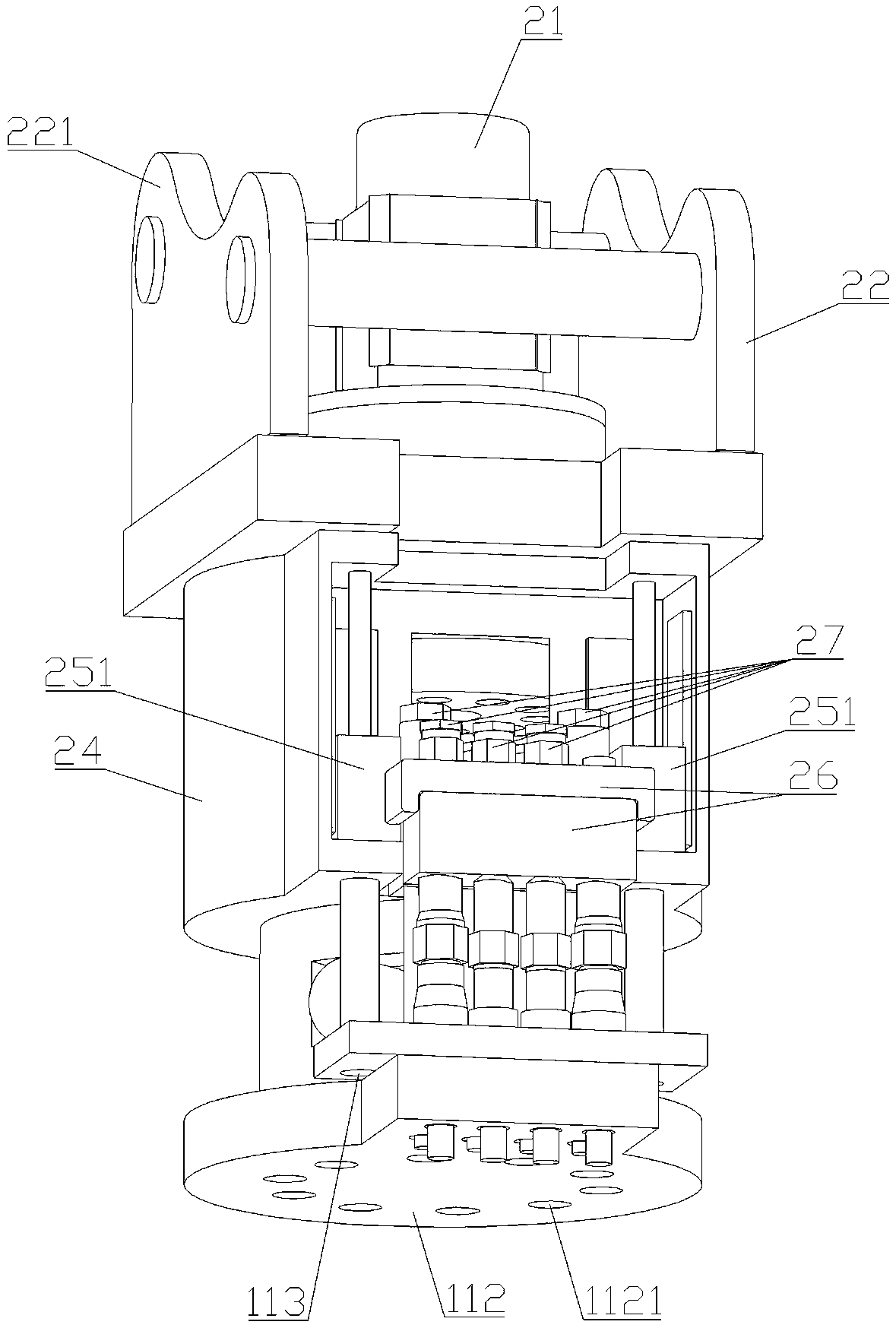
[0044] like Figure 1-7 As shown, the robot end tool quick change device includes a first assembly and a second assembly.

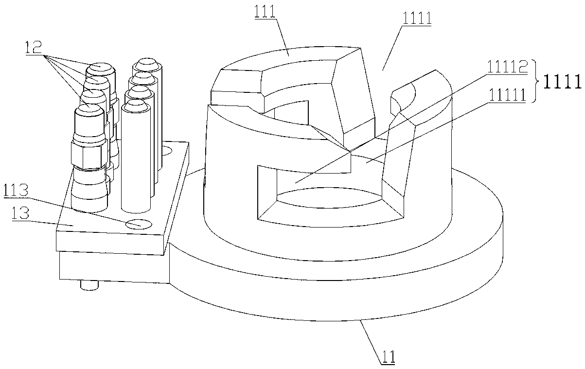
[0045] The first assembly includes a tool tray 11 , a male connector 12 and a male connector seat 13 .

[0046] One side of the tool tray 11 is provided with an engaging portion A, and the other side is provided with a tool connection surface 112 . The connecting portion A is an annular boss 111 fixed on the tool tray 11, and an L-shaped notch 1111 is provided on the annular boss. The L-shaped notch 1111 includes a vertical section 11111 and a horizontal section 11112 communicating with the vertical section 11111. The tool connection surface 112 is provided with a mounting hole A1121 for mounting a tool.

[0047] The male joint 12 is installed on the male joint seat 13 , and the male joint seat 13 is fixedly connected to the tool tray 11 .

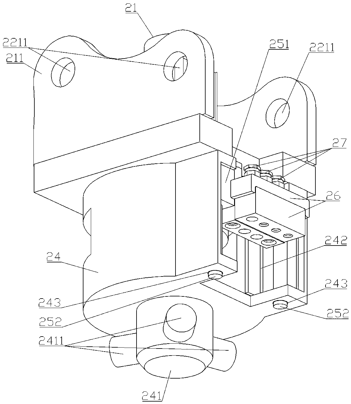
[0048] The second assembly includes a motor 21 , a connecting seat A22 , a rotating sleeve 23 , a connecting sea...


PUM


Abstract

The invention provides a rapid switching device and method for a robot end tool, and relates to the technical field of automatic switching of the robot end tool. The rapid switching device comprises afirst assembly and a second assembly, wherein the first assembly comprises a tool tray, a male joint and a male joint seat; the second assembly comprises a motor, a connecting base A, a rotating sleeve, a connecting base B, a female joint, a female joint seat and a butted separation assembly; when the first assembly and the second assembly are connected, the tool tray is connected with a connection part B of the connecting base B through a connection part A, and the butted separation assembly is used for locking the tool tray and driving the male joint and the female joint to be butted simultaneously, or unlocking the tool tray and driving the male joint and the female joint to be separated simultaneously. The rapid switching method for the robot end tool is applied to the rapid switchingdevice for the robot end tool and comprises a butting process and a dismounting process. The robot end tool can be automatically dismounted and mounted by remotely controlling a robot, the whole dismounting and mounting process is rapid, simple and convenient and has good reliability, and besides, no interference is produced between the male joint and the female joint.

Description

technical field [0001] The invention relates to the technical field of automatic switchover of robot end tools, in particular to a quick switchover device and a switchover method for robot end tools. Background technique [0002] Robots (especially multi-axis robots) have been widely used in various industries due to their flexibility, reliability and efficiency, and are gradually replacing manual operations. However, in the actual application process, it is often necessary for a robot to handle several different products or different processes, and the robot needs to be matched with several different end tools accordingly. Common end tools include buckets, hydraulic hammers, hydraulic shears, Hydraulic pliers, cutting machines, etc. At present, when replacing the end tool, manual disassembly and assembly are often required, and the steps are cumbersome and time-consuming. In some dangerous environments (such as nuclear radiation, high temperature, low temperature, etc.), ...

Claims


Application Information

Patent Timeline
Patent Type & Authority Applications(China)
IPC IPC(8): B25J19/00B25J9/00
CPCB25J19/00B25J9/0009
Inventor 邹树梁邓骞薛帅王湘江唐德文
Owner NANHUA UNIV
Why Eureka
Try Eureka