A rail grinding device adaptable to rails with different distances

A technology that adapts to different rails. It is applied in the direction of track, track laying, track maintenance, etc. It can solve the problems of reducing the smoothness of rails, poor rail smoothness, and unsuitable rails, etc., and achieve the effect of increasing the scope of application.

Active Publication Date: 2020-09-04
NANJING ZHONGXING TRACK EQUIP
View PDF7 Cites 0 Cited by
  • Summary
  • Abstract
  • Description
  • Claims
  • Application Information

AI Technical Summary

Problems solved by technology

[0002] With the continuous development of high-speed rail technology, the quality requirements of rails are getting higher and higher. Since the speed of high-speed rails, bullet trains, and subways is much higher than that of ordinary trains, the smoothness of rails is highly required, and the main factors that affect the smoothness of rails There are the following aspects: 1. After the main body of the rail is produced and formed, there will be many burrs on the surface, and the smoothness of the rail is poor; The remaining welding points are extremely uneven on the track, which affects the smoothness of the rail; 3. The rails in use may be corroded for a long time and may also produce rust spots, which reduces the smoothness of the rails; 4. The rails are exposed to the outside for a long time. There is a lot of dust attached to the surface, which reduces the smoothness of the rails. The existing rail grinding devices are often used for grinding rails of a single specification, and are often not suitable for rails of different specifications due to geographical terrain and other reasons.

Method used


Image

  • A rail grinding device adaptable to rails with different distances
  • A rail grinding device adaptable to rails with different distances
  • A rail grinding device adaptable to rails with different distances

Examples


Embodiment Construction

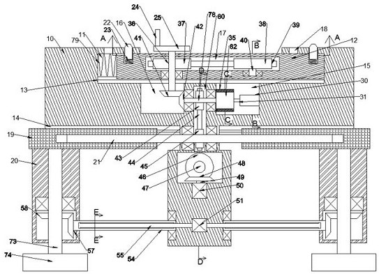
[0019] Combine below Figure 1-6 The present invention is described in detail, and for convenience of description, the orientations mentioned below are now stipulated as follows: figure 1 The up, down, left, right, front and back directions of the projection relationship itself are the same.

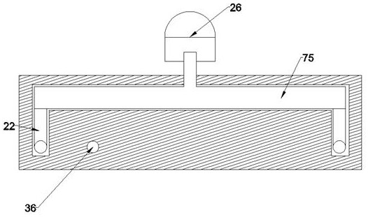
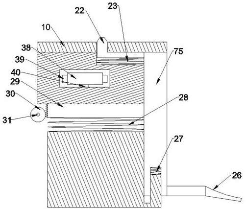
[0020] refer to Figure 1-6 According to an embodiment of the present invention, a rail grinding device that can adapt to different distance rails includes a fuselage 10, and the left and right sliding chambers 11 with upward openings are arranged in the fuselage 10, and the lower walls of the left and right sliding chambers 11 are provided with There are left and right slide rails 13, the left and right slide rails 13 are slidingly provided with left and right sliders 12, the left outer surface of the left and right sliders 12 is fixed with a slider spring 79, and a switch chamber is arranged below the left and right slide chambers 11 16. A through hole 18 for locking the left and rig...


PUM


Abstract

The invention discloses a rail grinding device capable of adapting to rails with different distances. The device comprises a machine body. A left-right sliding cavity with an upward opening is formedin the machine body. A left-right sliding rail is arranged on the lower wall of the left-right sliding cavity. A left-right slide block is arranged in the left-right sliding rail. A sliding block spring is fixedly arranged on the outer surface of the left side of the left-right sliding block. A switching cavity is formed below the left-right sliding cavity. A through hole for arranging a clampingposition is formed in the upper part of the left-right sliding cavity. A transmission cavity is formed in the right side of the switching cavity. A rotatable second rotating rod is arranged in the transmission cavity. A locking cavity is formed in the right side of the transmission cavity. The second rotating rod extends left and right into the switching cavity and the locking cavity. A brake clamping ring for locking is arranged in the locking cavity. After the distance between grinding knives is adjusted, the position between the grinding knives can be locked, and therefore, the situation inwhich the grinding quality is affected due to the fact that the distance between the grinding knives is changed due to vibration or other reasons in the grinding process is avoided.

Description

technical field [0001] The invention relates to the technical field of railways, in particular to a rail grinding device that can adapt to rails with different distances. Background technique [0002] With the continuous development of high-speed rail technology, the quality requirements of rails are getting higher and higher. Since the speed of high-speed rails, bullet trains, and subways is much higher than that of ordinary trains, the smoothness of rails is highly required, and the main factors that affect the smoothness of rails There are the following aspects: 1. After the main body of the rail is produced and formed, there will be many burrs on the surface, and the smoothness of the rail is poor; The remaining welding points are extremely uneven on the track, which affects the smoothness of the rail; 3. The rails in use may be corroded for a long time and may also produce rust spots, which reduces the smoothness of the rails; 4. The rails are exposed to the outside for...

Claims


Application Information

Patent Timeline
Patent Type & Authority Patents(China)
IPC IPC(8): E01B31/17
CPCE01B31/17
Inventor 不公告发明人
Owner NANJING ZHONGXING TRACK EQUIP
Why Eureka
Try Eureka