
Multifunctional integrated pump station

A multi-functional, pumping station technology, applied in pumping stations, parts of pumping devices for elastic fluids, pump elements, etc., can solve problems such as unfavorable transmission of water and liquid filtration, inability to purify water and liquid, and pipeline blockage, etc. Achieve the effects of increasing cleaning efficiency, avoiding pipe clogging and increasing service life

Inactive Publication Date: 2020-04-10
中新嘉创(江苏)环保科技发展有限公司
View PDF8 Cites 4 Cited by
  • Summary
  • Abstract
  • Description
  • Claims
  • Application Information

AI Technical Summary

Problems solved by technology

[0002] A pumping station is a device and project that can provide hydraulic power and pneumatic power with a certain pressure and flow rate. It is called a pump and pumping station project. Lifting equipment for sewage, rainwater, drinking water, and waste water. For the import and export of sewage, rainwater, drinking water, and waste water, most devices cannot purify water well.
[0003] However, most of the integrated pumping stations currently on the market do not have a filter device, which is not conducive to the filtration of the transmitted water, resulting in blockage of the pipeline during the operation of the device. Remote monitoring is not conducive to real-time observation of the operation of the device. Most of the sewage discharge and water outlet are in the same channel, which is not conducive to the working efficiency of the device and cannot achieve the effect of cleaning the inside of the device.

Method used


Image

  • Multifunctional integrated pump station
  • Multifunctional integrated pump station
  • Multifunctional integrated pump station

Examples


Embodiment Construction

[0023] The following will clearly and completely describe the technical solutions in the embodiments of the present invention with reference to the accompanying drawings in the embodiments of the present invention. Obviously, the described embodiments are only some, not all, embodiments of the present invention. Based on the embodiments of the present invention, all other embodiments obtained by persons of ordinary skill in the art without making creative efforts belong to the protection scope of the present invention.

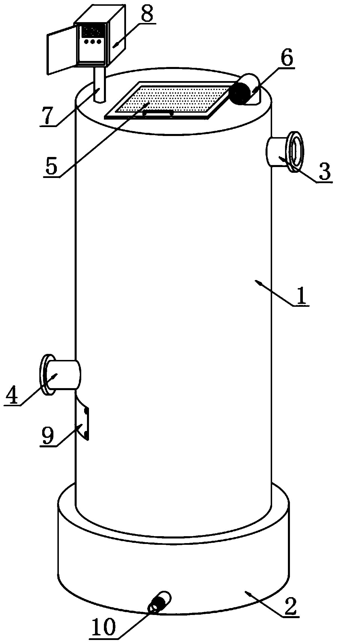
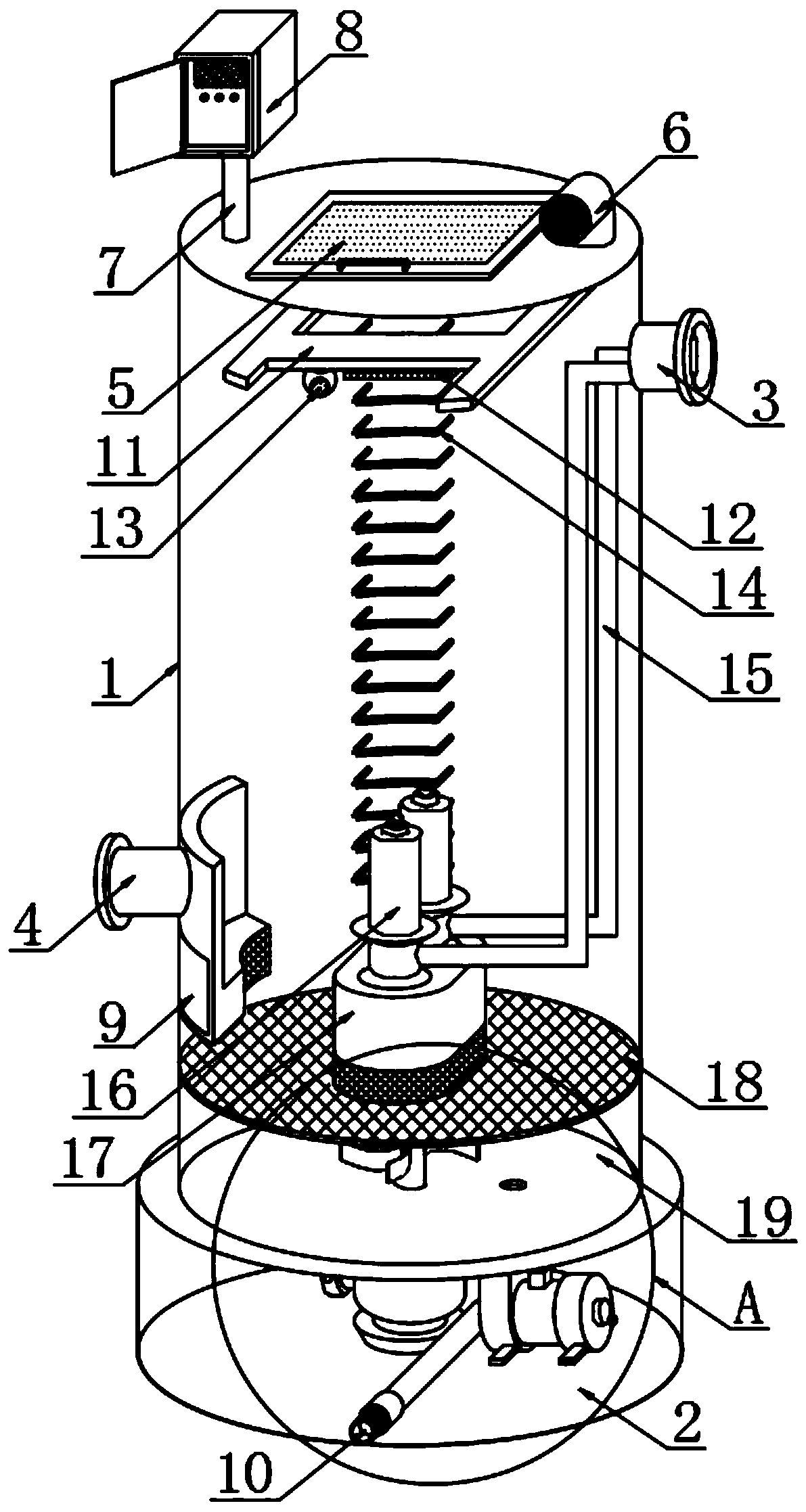
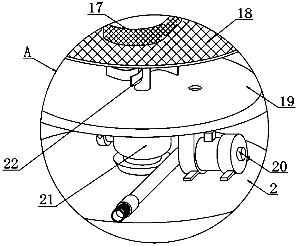
[0024] see Figure 1-5 , in an embodiment of the present invention, a multifunctional integrated pumping station includes a pumping station main body 1, a platform 2 is provided on the lower surface of the pumping station main body 1, a sewage outlet 10 is installed on the front surface of the platform 2, and the pumping station main body The outer surface of the lower end of 1 is welded with a water inlet 4, the outer surface of the lower end of the pump stat...


PUM


Abstract

The invention discloses a multifunctional integrated pump station, particularly relates to the technical field of integrated pump stations. The multifunctional integrated pump station comprises a pumpstation body. A table seat is arranged on the lower surface of the pump station main body. A drain outlet is formed in the front surface of the table seat. A water inlet is welded to the outer surface of the lower end of the pump station main body in a penetrating manner. A dirt removing plate is mounted at the portion, located at the lower position of the water inlet, of outer surface of the lower end of the pump station main body. A water outlet is welded to the outer surface of the upper end of the pump station main body in a penetrating manner. A top cover is rotationally mounted on the upper surface of the pump station main body. A gas outlet pipe is welded to one side of the upper surface of the pump station main body in a penetrating manner. A support rod is welded to the other side of the upper surface of the pump station main body. A control cabinet is mounted on the upper surface of the support rod. A stirring box is arranged at the lower end in the pump station main body. According to the integrated pump station, a plurality of filtering devices are arranged, the device can be remotely monitored in the operating process, and the sewage discharging and water outlet of the device are performed through different channels.

Description

technical field [0001] The invention relates to the technical field of an integrated pumping station, in particular to a multifunctional integrated pumping station. Background technique [0002] A pumping station is a device and project that can provide hydraulic power and pneumatic power with a certain pressure and flow rate. It is called a pump and pumping station project. Lifting equipment for lifting sewage, rainwater, drinking water, and waste water. For the import and export of sewage, rainwater, drinking water, and waste water, most devices cannot purify water well. [0003] However, most of the integrated pumping stations currently on the market do not have a filter device, which is not conducive to the filtration of the transmitted water, resulting in blockage of the pipeline during the operation of the device. Remote monitoring is not conducive to real-time observation of the operation of the device. Most of the sewage discharge and water outlet are in the same ch...

Claims


Application Information

Patent Timeline
IPC IPC(8): E03B5/00E03F5/22F04B49/06F04B53/20
CPCE03B5/00E03F5/22F04B49/065F04B53/20
Inventor 徐善平
Owner 中新嘉创(江苏)环保科技发展有限公司
Learn More