Pole erecting device for electric power laying and use method of pole erecting device

A pole device and electric power technology, which is applied in the field of pole devices for power laying, can solve problems such as increased operational difficulty, high labor intensity, and damage to cement poles, so as to improve stability and safety, reduce difficulty in removal, Avoid the effect of coagulation instability

Active Publication Date: 2020-04-10
国网山东省电力公司沂水县供电公司
View PDF12 Cites 4 Cited by
  • Summary
  • Abstract
  • Description
  • Claims
  • Application Information

AI Technical Summary

Problems solved by technology

[0004] 1. The labor intensity is high, requiring a lot of manpower and material resources, and each force direction needs to cooperate with each other to complete the work smoothly. If one or several directions do not cooperate, the cement pole will be skewed or even fall to the ground. If the rod is broken and damaged, there will be safety hazards for personnel, which not only increases the difficulty of operation but also poses safety hazards;
[0005] 2. If the position of the hoop is at the lower position of the pole body, it is easy to remove it after the cement pole is erected, but when the pole is erected, the resistance moment of the cement pole is relatively large, so it is more laborious, and it is not easy to maintain the cement pole after it is erected. Stable, and if the position of the hoop is at a higher position on the pole body, although the difficulty of operation is reduced, it is also easy to maintain the stability of the cement pole after it is erected, but it is inconvenient to remove the hoop

Method used


Image

  • Pole erecting device for electric power laying and use method of pole erecting device
  • Pole erecting device for electric power laying and use method of pole erecting device
  • Pole erecting device for electric power laying and use method of pole erecting device

Examples


Embodiment Construction

[0033] The following will clearly and completely describe the technical solutions in the embodiments of the present invention with reference to the accompanying drawings in the embodiments of the present invention. Obviously, the described embodiments are only some, not all, embodiments of the present invention. Based on the embodiments of the present invention, all other embodiments obtained by persons of ordinary skill in the art without creative efforts fall within the protection scope of the present invention.

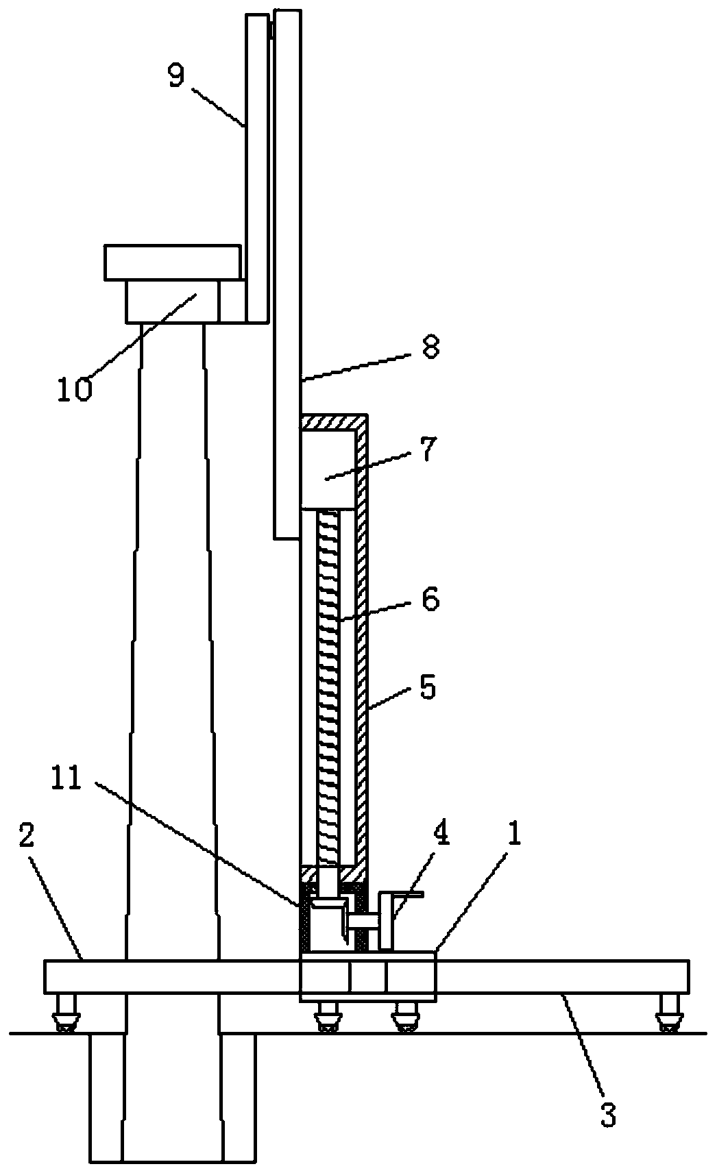
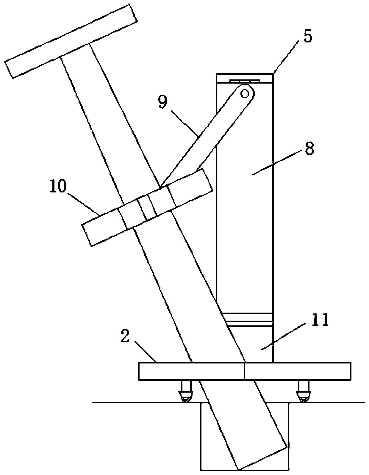
[0034] see Figure 1 to Figure 8 , the present invention provides a technical solution: a pole device for power laying, including a base 1, a front support 2 and a rear support 3 are movably connected to the base 1, and a vertical upward stand 5 is fixed on the base 1 , and the vertical frame 5 is threadedly connected with a lifting frame 8 that makes the cement rod stand up, the cement rod can be erected from a flat state to a vertical state by the lifting frame 8...


PUM


Abstract

The invention relates to the field of electric power laying tools, in particular to a pole erecting device for electric power laying and a use method of the pole erecting device. The pole erecting device comprises a base, a front bracket and a rear bracket are movably connected to the base, a vertical upward stand is fixed to the base, a lifting bracket for erecting a cement pole is connected with the stand in a threaded mode, a pull rod is connected at the upper end of the lifting bracket in a hinged mode, and a pole clamping mechanism is connected at the lower end of the pull rod in a hinged mode; and a first hoop frame is fixed on the pole clamping mechanism, which is movably connected with a second hoop frame, and a stop part is fixed on the second hoop frame. According to the pole erecting device for electric power laying and the use method of the pole erecting device, with rising operation of the cement pole, the time and the labor are saved, the labor intensity is reduced, no need for many people to participate in, control is convenient, and the difficulty of operation is reduced; and moreover, the cement pole can be clamped and erected through the pole clamping mechanism with a stop back function, thereby improving the stability and safety when the cement pole is erected, and the first hoop frame and the second hoop frame are convenient to remove from the erected cement pole.

Description

technical field [0001] The invention relates to the field of power laying tools, in particular to a pole device for power laying and a method for using the same. Background technique [0002] In the early days of our country, wooden poles and cement poles were often used as supporting structures for laying electric wires. At present, with the upgrading and transformation of transmission lines, these wooden poles and cement poles can no longer meet the requirements of line erection, but cement is still mainly needed in rural residential power lines. It is also one of the power facilities closest to end-use customers. Cement rods are usually tapered rods with a thick bottom and a thin top. The existing method in the erection and fixing operation is to use a metal hoop to fix the cement rod and use multiple stretches. One end is fixed on the hoop and the other end is fixed by the worker. Or other equipment pulls and stretches from all directions to erect the cement pole. [0...

Claims


Application Information

Patent Timeline
Patent Type & Authority Applications(China)
IPC IPC(8): E04H12/34
CPCE04H12/347
Inventor 吴乾臻吴恭蕊
Owner 国网山东省电力公司沂水县供电公司
Why Eureka
Try Eureka