Hydraulic engine and working method thereof

A hydraulic engine, engine technology, applied in engine control, machine/engine, mechanical equipment, etc., can solve the problems of difficult to achieve constant volume combustion, easy to change engine compression ratio, etc.

Inactive Publication Date: 2020-04-10
烟台小米机械技术有限公司
View PDF5 Cites 0 Cited by
  • Summary
  • Abstract
  • Description
  • Claims
  • Application Information

AI Technical Summary

Problems solved by technology

[0003] The invention provides a hydraulic engine and its working method, aiming at solving the problems that the compression ratio of the existing engine is easy to change and it is difficult to achieve constant volume combustion.

Method used


Image

  • Hydraulic engine and working method thereof
  • Hydraulic engine and working method thereof
  • Hydraulic engine and working method thereof

Examples


Embodiment Construction

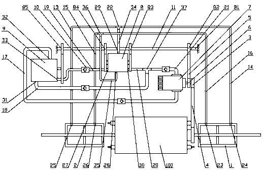
[0050] The embodiment of the present invention provides a hydraulic engine and its working method. By combining the engine with two sets of piston assemblies and the hydraulic system installed with a valve plate and a rotary valve, the compression ratio is controlled by the rotary valve and realized by the valve plate. Constant-volume combustion can effectively solve the problems that the existing engine compression ratio is difficult to control and difficult to achieve constant-volume combustion.

[0051] In order to better understand the technical solution of the present invention, the technical solution of the present invention is described in detail below in conjunction with the accompanying drawings and embodiments:

[0052] Embodiments of the present invention provide a hydraulic engine and its working method, such as figure 1 As shown, it mainly includes an engine main body 100, the right side of the engine main body 100 is connected with a connecting wheel A106, and th...


PUM


Abstract

The invention relates to a hydraulic engine and a working method thereof. The hydraulic engine primarily comprises an engine main body. An oil cylinder A is connected to the right side of the engine main body, an oil cylinder B is connected to the left side of the engine main body, a connecting wheel A is arranged on the engine main body, the connecting wheel A is connected to a hydraulic pump, anoil outlet of the hydraulic pump is connected to a rotary valve through a pipeline, an oil inlet of the hydraulic pump is connected to a valve plate through a pipeline, a connecting wheel D is arranged on the rotary valve, a connecting wheel B and a connecting wheel C are arranged on the valve plate, a transmission wheel B is arranged on the hydraulic pump, and the transmission wheel B, the connecting wheel B, the connecting wheel B, the connecting wheel C and the connecting wheel D are connected to a transmission assembly. By combining the engine of a special structure with a hydraulic system, problems that an existing engine is non-constant in compression ratio and is hard to achieve constant volume combustion and the like can be solved effectively.

Description

technical field [0001] The invention belongs to the field of engines, and in particular relates to a hydraulic engine and a working method thereof. Background technique [0002] The compression ratio is a very important concept in the engine. The compression ratio indicates the degree of compression of the gas. It is the ratio of the volume of the gas before compression to the volume of the gas after compression, that is, the ratio of the total volume of the cylinder to the volume of the combustion chamber is called the compression ratio. , The compression position of the piston in the existing engine is generally controlled by the cooperation of the position sensor and the solenoid valve. Due to the time difference in the signal transmission of the solenoid valve, the engine compression ratio is constantly changing, which affects the engine performance. In addition, constant volume combustion is also a very important concept in engines. Constant volume combustion refers to ...

Claims


Application Information

Patent Timeline
Patent Type & Authority Applications(China)
IPC IPC(8): F02B75/12F02B75/26F02D15/00F02B63/06
CPCF02B63/06F02B75/12F02B75/26F02D15/00
Inventor 姚长水
Owner 烟台小米机械技术有限公司
Why Eureka
Try Eureka