Fan head swing angle control device

An angle control, fan shaking head technology, applied in pump control, pump device, non-variable-capacity pump, etc., can solve the problems of physical discomfort, inability to adjust the swing, easy to cause headache and nasal congestion, etc., to achieve easy connection and simple device structure. , to achieve the effect of adjustability

Inactive Publication Date: 2020-04-10
张一茗
View PDF6 Cites 0 Cited by
  • Summary
  • Abstract
  • Description
  • Claims
  • Application Information

AI Technical Summary

Problems solved by technology

[0002] At present, the use status of electric fans includes two types: fixed air supply and swing head air supply. The first fixed air supply method is usually selected when only one person uses it. Users often position the electric fan so that it is directly facing the body. Blowing air, this long-term direct air blowing method often causes physical discomfort, and it is easy to cause symptoms such as headache and nasal congestion; the second swinging head blowing is suitable for use when many people live together. Cool wind can be blown everywhere. Since the swing of the electric fan head is determined by the eccentric block, no matter there are only two people or more than three people, the swing range cannot be adjusted. Therefore, when there are few people , it will cause the disadvantage of poor air supply efficiency of the electric fan due to the excessive swing

Method used


Image

  • Fan head swing angle control device
  • Fan head swing angle control device
  • Fan head swing angle control device

Examples


Embodiment Construction

[0018] In order to make the implementation technical means, creative features, objectives and effects of the present invention easy to understand, the present invention will be further elaborated below in conjunction with specific illustrations.

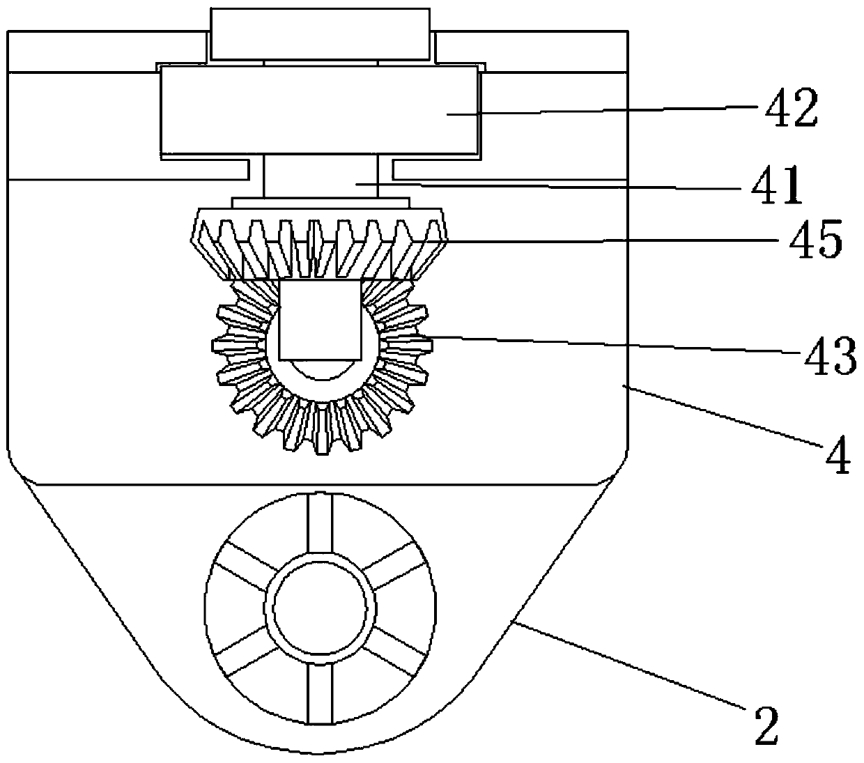
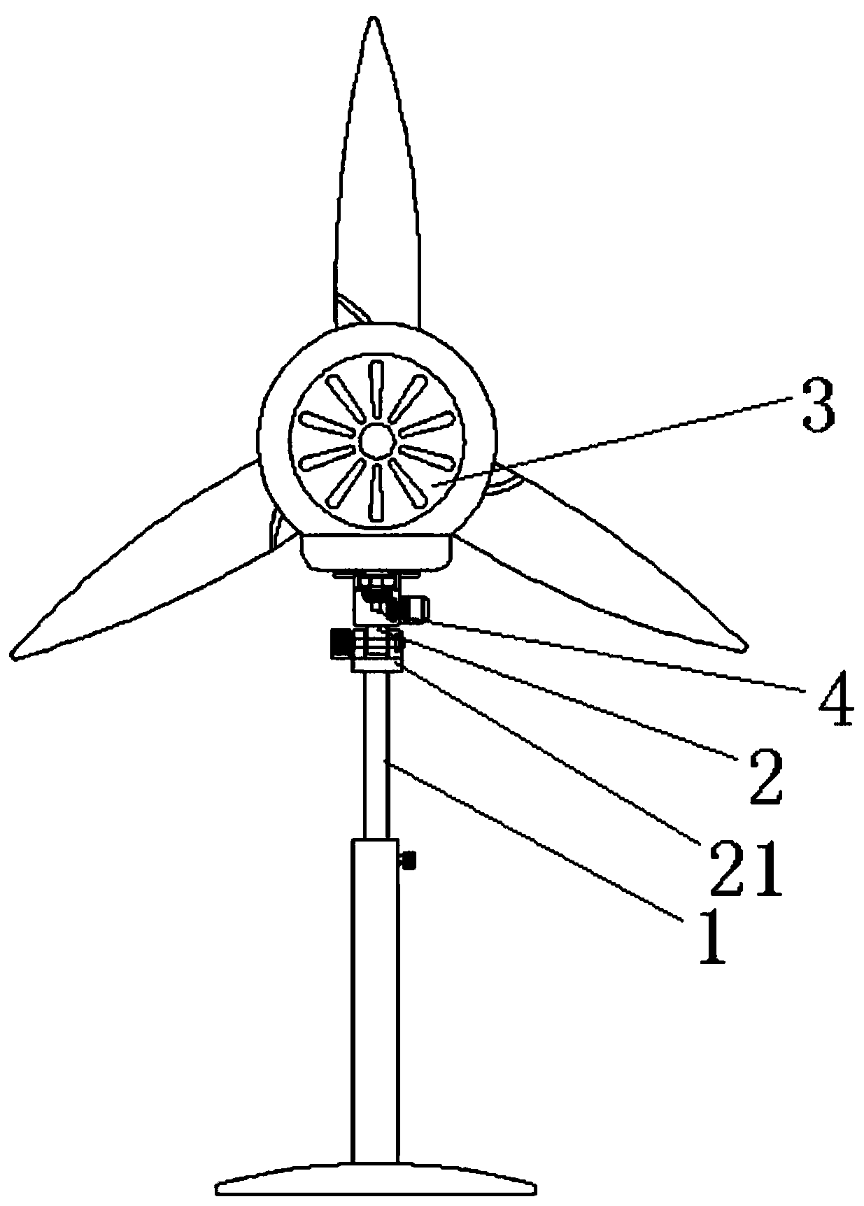
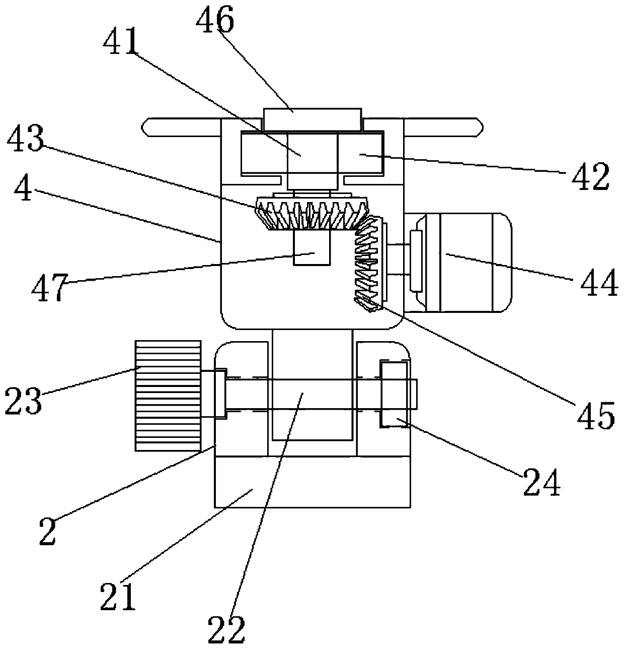
[0019] Such as Figure 1~4 as shown,

[0020] This embodiment provides a fan swing angle control device, including a turntable 2 installed on the support rod 1, a turntable 4 arranged on the upper end of the turntable 2 and connected to the machine head 3, and installed on the turntable 4 for driving the machine. The driving device for the rotation of the head 3; the turning seat 4 and the turntable 2 are integrally molded and molded, and the turning seat 4 includes a support shaft 41 fixedly connected with the machine head 3, a bearing seat 42 connected in rotation with the support shaft 41 and mounted on The first bevel gear 43 that the lower end of the support shaft 41 is connected with the driving device; The corresponding posi...


PUM


Abstract

The invention provides a fan head swing angle control device. The fan head swing angle control device comprises a rotary disc installed on a supporting rod, a rotating base arranged at the upper end of the rotary disc and connected with a fan head, and a driving device installed on the rotating base and used for driving the fan head to rotate; the rotating base and the rotary disc are integrally formed by mould casting; and the rotating base comprises a supporting shaft fixedly connected with the fan head, a bearing pedestal rotationally connected with the supporting shaft, and a first bevel gear installed at the lower end of the supporting shaft and connected with the driving device. The fan head is fixed to the rotating base through the supporting shaft in a rotary connection manner, a supporting column is in transmission connection with a second bevel gear of the driving device by installation of the first bevel gear to drive the fan head to rotate, a driving motor controls left andright angle adjustment of the fan head by forward and reverse rotation, and the adjustability of the fan swing angle is achieved. The fan head swing angle control device is simple in structure, can be conveniently connected with the fan head and can realize angle control in a large range.

Description

technical field [0001] The invention relates to the technical field of fan equipment, in particular to a fan swing angle control device. Background technique [0002] At present, the use status of electric fans includes two types: fixed air supply and swing head air supply. The first fixed air supply method is usually selected when only one person uses it. Users often position the electric fan so that it is directly facing the body. Blowing air, this long-term direct air blowing method often causes physical discomfort, and it is easy to cause symptoms such as headache and nasal congestion; the second swinging head blowing is suitable for use when many people live together. Cool wind can be blown everywhere. Since the swing of the electric fan head is determined by the eccentric block, no matter there are only two people or more than three people, the swing range cannot be adjusted. Therefore, when there are few people , it will cause the disadvantage of poor air supply effi...

Claims


Application Information

Patent Timeline
Patent Type & Authority Applications(China)
IPC IPC(8): F04D25/10F04D27/00
CPCF04D25/105F04D27/00
Inventor 张一茗
Owner 张一茗
Why Eureka
Try Eureka