Pressurization detection device of pressure sensor

A pressure sensor and detection device technology, applied in the field of sensors, can solve the problems of low manual work efficiency, low accuracy, and poor comprehensiveness, and achieve the effects of improving detection accuracy and pass rate, high work efficiency, and high detection accuracy

Active Publication Date: 2020-04-10
英赛维思智能设备(武汉)有限公司
View PDF6 Cites 2 Cited by
  • Summary
  • Abstract
  • Description
  • Claims
  • Application Information

AI Technical Summary

Problems solved by technology

[0002] A pressure sensor is a device or device that can sense pressure signals and convert the pressure signals into usable output electrical signals according to certain rules. With the wide application of pressure sensors, it is very important to determine how to detect pressure sensors. Usually there are bridges There are three methods: road detection, zero point detection and pressure detection. Among them, the pressure detection is to supply power to the sensor, pressurize the air guide hole of the sensor, and use the voltage of the multimeter to detect the voltage change of the output terminal of the sensor. If the relative pressure of the pressure sensor The sensitivity is very high, and the amount of change will be obvious. However, the existing pressurized detection device performs random inspection on the sensor, which is poor in comprehensiveness and increases the number of unqualified products. In addition, the existing pressurized detection process is usually carried out manually and assisted by a pressure gauge. The efficiency of manual work is low, and there are human errors in the detection, and the accuracy is low

Method used


Image

  • Pressurization detection device of pressure sensor
  • Pressurization detection device of pressure sensor
  • Pressurization detection device of pressure sensor

Examples


Embodiment Construction

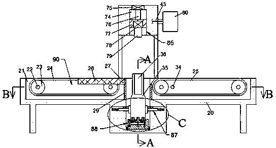
[0020] Combine below Figure 1-Figure 5 The present invention is described in detail, and for convenience of description, the orientations mentioned below are now stipulated as follows: figure 1 The up, down, left, right, front and back directions of the projection relationship itself are the same.

[0021] The present invention relates to a pressurization detection device of a pressure sensor, which is mainly used for pressure sensor detection. The present invention will be further described below in conjunction with the accompanying drawings of the present invention:

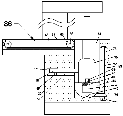
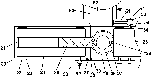
[0022] A pressurized detection device for a pressure sensor according to the present invention includes a body 20, a conveying cavity 21 is arranged in the body 20, a conveying device 90 is arranged in the conveying chamber 21, and the conveying device 90 includes a rotatable The first conveyor belt 24 and the second conveyor belt 25, the first conveyor belt 24 and the second conveyor belt 25 turn in the same...


PUM


Abstract

The invention discloses a pressurization detection device of a pressure sensor. The detection device comprises a machine body, a conveying cavity is formed in the machine body; and a conveying deviceis arranged in the conveying cavity. The conveying device comprises a first conveying belt and a second conveying belt which can rotate. The first conveying belt and the second conveying belt have thesame rotating directions and are used for conveying sensors. According to the invention, the conveying device drives the sensor to convey rightwards; in the delivery process, the pressure of the sensor is detected through the detection device and a pressurizing device; the detection process is in full automation; each sensor can be detected, so that the detection accuracy and the pass percentageare improved. Besides, the detected qualified sensors are directly output rightwards to be packaged, the unqualified sensors are output backwards to be recycled in a centralized mode, so that automatic rejecting work of defective products is realized. The device is high in working efficiency and detection precision, automatic in operation and convenient to use.

Description

technical field [0001] The invention relates to the technical field of sensors, in particular to a pressure detection device for a pressure sensor. Background technique [0002] A pressure sensor is a device or device that can sense pressure signals and convert the pressure signals into usable output electrical signals according to certain rules. With the wide application of pressure sensors, it is very important to determine how to detect pressure sensors. Usually there are bridges There are three methods: road detection, zero point detection and pressure detection. Among them, the pressure detection is to supply power to the sensor, pressurize the air guide hole of the sensor, and use the voltage of the multimeter to detect the voltage change of the output terminal of the sensor. If the relative pressure of the pressure sensor The sensitivity is very high, and the amount of change will be obvious. However, the existing pressurized detection device performs random inspectio...

Claims


Application Information

Patent Timeline
Patent Type & Authority Applications(China)
IPC IPC(8): G01L27/00
CPCG01L27/007
Inventor 不公告发明人
Owner 英赛维思智能设备(武汉)有限公司
Why Eureka
Try Eureka