An automatic anti-fogging double-lens helmet and its use method

A double-lens and helmet technology, applied in helmets, helmet caps, applications, etc., can solve the problems of easy wear, poor anti-fogging effect, and easy corrosion, and achieve the goals of reducing energy consumption, reliable anti-fogging, and improving safety Effect

Active Publication Date: 2022-06-21
ZHONGYUAN ENGINEERING COLLEGE
View PDF6 Cites 0 Cited by
  • Summary
  • Abstract
  • Description
  • Claims
  • Application Information

AI Technical Summary

Problems solved by technology

[0003] Aiming at the technical problem that the anti-fogging technology used in the existing helmets is easy to wear and corrode, resulting in poor anti-fogging effect, the present invention proposes an automatic anti-fogging double-lens helmet and its use method. The defogging system enables riders to focus more on road condition analysis in cold weather, without having to repeatedly adjust the helmet to defog, ensuring the safety of riders

Method used


Image

  • An automatic anti-fogging double-lens helmet and its use method
  • An automatic anti-fogging double-lens helmet and its use method
  • An automatic anti-fogging double-lens helmet and its use method

Examples


Embodiment 1

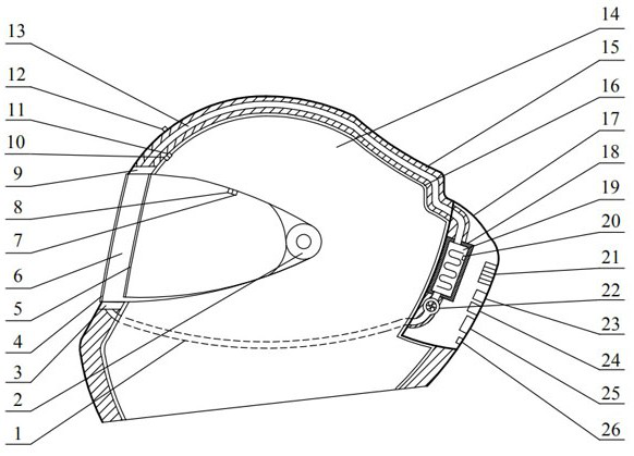
[0035] Example 1, as figure 1As shown, the present invention provides an automatic anti-fogging double-lens helmet, including a helmet body on which an outer lens 4 and an inner lens 5 are mounted, the outer lens 4 has an anti-scratch function, and the inner lens 5 has an anti-scratch function. Direct sunlight function, and the inner lens 5 is located inside the outer lens 4, the outer lens 4 and the inner lens 5 are movably connected to the helmet body through the connection knob 2, so that the outer lens 4 and the inner lens 5 move up and down relative to the helmet body. There is a cavity 6 between the outer lens 4 and the inner lens 5, the cavity 6 is connected with the anti-fogging mechanism, the anti-fogging mechanism is connected with the automatic control circuit, and the anti-fogging mechanism and the automatic control circuit are paired with each other. Anti-fogging can be achieved by heating the air in the cavity formed by the lens. The anti-fogging mechanism inclu...

Embodiment 2

[0039] Embodiment 2, the present invention provides a kind of use method of automatic anti-fogging double lens helmet, and its steps are as follows:

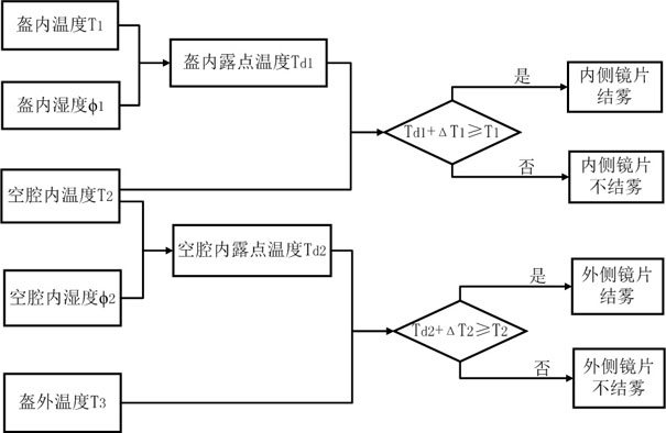
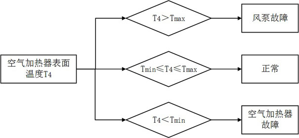
[0040] S1. When the outdoor temperature is low, manually close the power switch 26; the first temperature sensor 10, the first humidity sensor 11, the second temperature sensor 7, the second humidity sensor 8, the third temperature sensor 12 and the fourth temperature sensor 20 The electrical signals of the measured temperature and humidity are transmitted to the controller 25, and the controller 25 processes the input electrical signals and judges whether the inner side of the outer lens 4 and the inner side of the inner lens 5 are in a fogging state and whether there is an equipment failure: such as figure 2 As shown, the temperature T inside the helmet measured by the controller 25 through the first temperature sensor 10 and the first humidity sensor 11 1 and the humidity inside the helmet φ 1 Calculate the dew point temper...


PUM


Abstract

The present invention proposes an automatic anti-fogging double-lens helmet and its use method. The double-lens helmet includes a helmet body, an outer lens and an inner lens are installed on the helmet body, and the inner lens is located inside the outer lens; the outer lens A cavity is provided between the inner lens and the cavity, the cavity is connected with the anti-fog mechanism, and the anti-fog mechanism is connected with the automatic control circuit. The invention has both anti-fog and anti-sunlight functions, not only realizes automatic, efficient and reliable anti-fog through the cooperation of anti-fog mechanism and automatic control circuit, and significantly improves the safety of helmet use; The cavity formed by the lens can achieve a significant reduction in energy consumption and a significant improvement in safety at the same time, thereby effectively solving the problem of fogging on the inside of the helmet lens when the driver wears the helmet in cold weather or rainy days, which seriously affects driving safety.

Description

technical field [0001] The invention relates to the technical field of automatic control and helmet safety, in particular to an automatic anti-fogging double-lens helmet and a use method. Background technique [0002] In order to cope with the current situation of traffic congestion and difficult parking, electric vehicles or motorcycles have become the preferred means of transportation for many people. With the enhancement of safety awareness, when choosing electric vehicles or motorcycles as travel tools, cyclists will wear helmets. In cold weather and rainy days, due to the temperature difference between the inside and outside of the helmet and the air humidity inside the helmet, the inside of the helmet lens is prone to fog. The judgment of the situation may result in a traffic accident. At present, the commonly used anti-fogging technology is to spray an anti-fogging agent or paste an anti-fogging film on the inner side of the helmet lens, but it has shortcomings such...

Claims


Application Information

Patent Timeline
Patent Type & Authority Patents(China)
IPC IPC(8): A42B3/24
CPCA42B3/245
Inventor 巨福军范晓伟朱彩霞王方李志强宋昊展单一森任鹏翔周晓磊
Owner ZHONGYUAN ENGINEERING COLLEGE
Why Eureka
Try Eureka