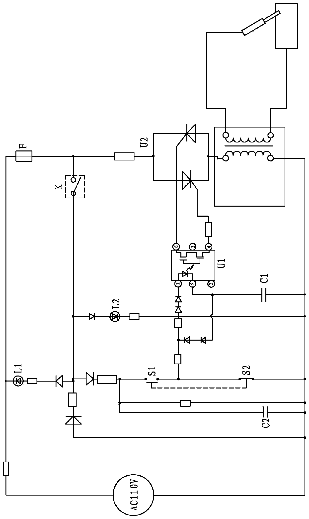
Welding gun control circuit

A technology for controlling circuits and welding torches, applied in the directions of manufacturing tools, welding rod characteristics, welding equipment, etc., can solve problems such as long welding time, and achieve the effect of avoiding excessive welding time

Pending Publication Date: 2020-04-14
JIANGMEN BOSJOB
View PDF0 Cites 0 Cited by
  • Summary
  • Abstract
  • Description
  • Claims
  • Application Information

AI Technical Summary

Problems solved by technology

For this reason, the present invention proposes a welding torch control circuit, which controls the welding time through capacitor discharge, and solves the problem that the existing welding torch easily causes the welding time to be too long

Method used


Image

  • Welding gun control circuit

Examples


Embodiment Construction

[0013] Embodiments of the present invention are described in detail below, examples of which are shown in the drawings, wherein the same or similar reference numerals designate the same or similar elements or elements having the same or similar functions throughout. The embodiments described below by referring to the figures are exemplary only for explaining the present invention and should not be construed as limiting the present invention.

[0014] In the description of the present invention, it should be understood that the orientation descriptions, such as up, down, front, back, left, right, etc. indicated orientations or positional relationships are based on the orientations or positional relationships shown in the drawings, and are only In order to facilitate the description of the present invention and simplify the description, it does not indicate or imply that the device or element referred to must have a specific orientation, be constructed and operated in a specific ...


PUM


Abstract

The invention discloses a welding gun control circuit which comprises a power supply, an output loop and a switch control loop. The output loop comprises an output controller U2, wherein the output controller U2 controls the output loop to be connected or disconnected; the switch control loop comprises a control chip U1, a first control switch S1, a second control switch S2 and an energy storage capacitor C1, wherein the output end of the control chip U1 is connected with the control end of the output controller U2; the first input end of the control chip U1 is connected with a high level through the first control switch S1, and the first input end of the control chip U1 is connected with a low level through the second control switch S2; the second input end of the control chip U1 is connected with one end of the energy storage capacitor C1; and the second input end of the control chip U1 is further connected with the first input end of the control chip U1. According to the scheme, theenergy storage capacitor C1 is used for controlling the working time of the output loop, so that the maximum welding time of a welding gun is controlled, and adverse effects caused by too long welding time are effectively avoided.

Description

technical field [0001] The invention relates to the field of welding technology, in particular to a welding torch control circuit. Background technique [0002] When a conventional welding torch is used for welding, the current output is controlled by the torch switch. When the torch switch is pressed, the current will be output all the time for the operator to weld; when the operator wants to stop welding, the torch switch is released to stop the welding. current output. The length of welding time is completely controlled by the operator. For some inexperienced operators, it is easy to cause the welding time to be too long during welding, which will lead to poor welding effect and blackened weldments. Even experienced welders, after a long time of concentrated welding work, will find it difficult to control the length of welding. Contents of the invention [0003] The present invention aims to solve at least one of the technical problems existing in the prior art. The...

Claims


Application Information

Patent Timeline
IPC IPC(8): B23K9/10B23K9/28
CPCB23K9/1043B23K9/28
Inventor 翁良轩翁敏翔
Owner JIANGMEN BOSJOB
Why Eureka
Try Eureka