Shell machining process

A processing technology and shell technology, applied in metal processing equipment, metal processing mechanical parts, manufacturing tools, etc., can solve problems such as inconvenient clamping and positioning, inability to effectively ensure production and processing efficiency, and difficult to guarantee processing accuracy.

Inactive Publication Date: 2020-04-14
SHENGRUI TRANSMISSION
View PDF4 Cites 4 Cited by
  • Summary
  • Abstract
  • Description
  • Claims
  • Application Information

AI Technical Summary

Problems solved by technology

[0002] Existing technologies such as figure 1 When processing the shell shown in the figure, the shell has front and rear end surfaces and side surfaces, and both the front and rear end surfaces and one side surface need to be processed. In

Method used


Image

  • Shell machining process
  • Shell machining process
  • Shell machining process

Examples


Embodiment Construction

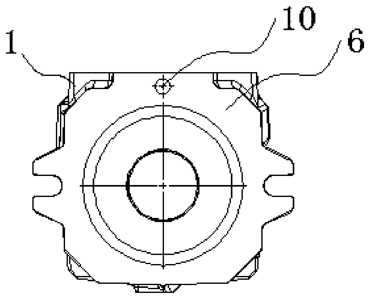
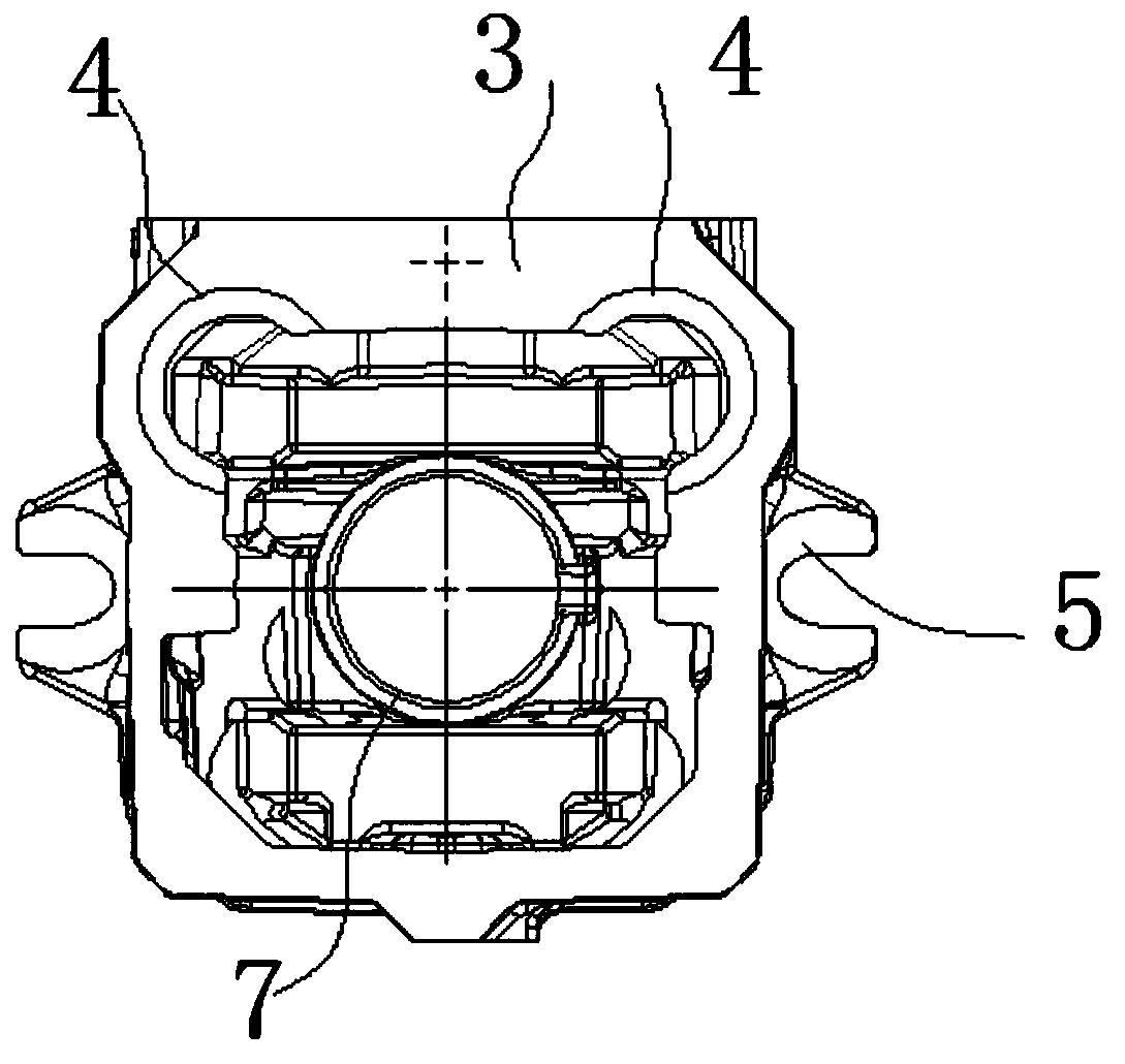
[0021] Such as figure 1 with figure 2 As shown, a shell processing technology includes the following steps:

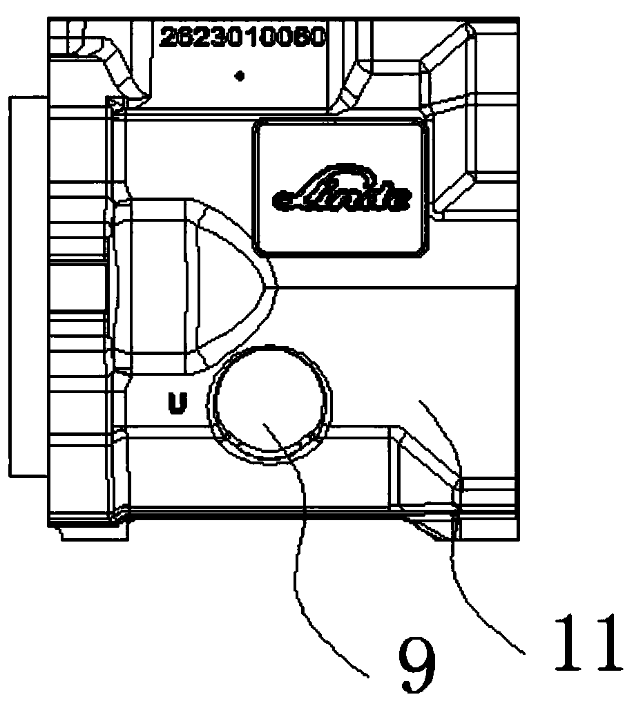
[0022] Step 1: casting blank, such as Figure 1-Figure 5 As shown, the blank 1 has an auxiliary pressing boss 2, and the auxiliary pressing boss is arranged on the side surface between the front end surface and the rear end surface of the blank, and the clamp clamps the blank on the auxiliary pressing boss. On the fixture, perform rough milling on the rear end face 3 of the blank 1;

[0023] Step 2: use the rear end face 3 and at least two rear end positioning holes 4 on the rear end face to position and process the front end face 6;

[0024] Step 3: use the rear end face in step 2 and at least two rear end positioning holes 4 on the rear end face for positioning, and mill the rear surface of the ear 5 on the side surface of the blank;

[0025] Step 4: Use the front end face 6 and at least two front positioning holes 10 on the front end face for positioning, finis...


PUM


Abstract

The invention discloses a shell machining process, which comprises the steps that firstly, a blank is cast, the blank is provided with an auxiliary pressing boss, a clamp clamps the blank on the clampthrough the auxiliary pressing boss, and rough milling is conducted on the rear end face of the blank; secondly, the front end face is positioned and machined through the rear end face and at least two rear end positioning holes in the rear end face; thirdly, the positioning in the second step is adopted, and the rear surfaces of lugs on the side surfaces of the blank are milled; fourthly, the front end face and at least two front end positioning holes in the front end face are adopted for positioning, the rear end face is finely milled, and a center hole in the front end face is bored; and fifthly, the positioning in the fourth step is adopted, the first side surface is milled, and a threaded hole in the second side surface is machined. The machining in the second step and the third stepcan be carried out through one-time clamping, the machining in the fourth step and the fifth step can be carried out after the blank is dismounted and clamped again after the third step is finished,the blank clamping frequency is effectively reduced, and the precision and the machining efficiency are improved.

Description

technical field [0001] The invention relates to a casing processing technology. Background technique [0002] Existing technologies such as figure 1 When processing the shell shown in the figure, the shell has front and rear end surfaces and side surfaces, and both the front and rear end surfaces and one side surface need to be processed. In the prior art, when processing such shell parts, there is inconvenience in clamping and positioning. The defect that the processing accuracy is not easy to be guaranteed cannot effectively guarantee the production and processing efficiency. Contents of the invention [0003] In order to make up for the above shortcomings, the present invention provides a shell processing technology that can effectively ensure processing accuracy and efficiency. [0004] The technical solution of the present invention is: a shell processing technology, comprising the following steps: [0005] Step 1: casting a blank, the blank has an auxiliary pressi...

Claims


Application Information

Patent Timeline
IPC IPC(8): B23P15/00B23Q3/06
CPCB23P15/00B23Q3/06
Inventor 杜泽通李建杨培友田立明张东生王福运刘卫朋
Owner SHENGRUI TRANSMISSION
Why Eureka
Try Eureka