
Machine tool base mechanism of small engraving and milling machine

A technology of engraving machines and machine tools, which is applied to large fixed members, metal processing machinery parts, metal processing equipment, etc., can solve the problems of no buffer mechanism, affect the stability of equipment, generate noise, etc., to achieve less difficulty in installation and adjustment, and improve the Processing stability and vibration reduction effect

Inactive Publication Date: 2020-04-14
温月生
View PDF0 Cites 0 Cited by
  • Summary
  • Abstract
  • Description
  • Claims
  • Application Information

AI Technical Summary

Problems solved by technology

[0002] Existing engraving machine tool bases generally do not have a buffer mechanism, which will generate a lot of vibration and noise during operation, and will easily affect the stability of the equipment;
[0003] At the same time, the moving mechanism of the upper support frame of the existing machine tool generally uses two transmission screws to rotate to realize the movement, and the two transmission screws are synchronously driven by two motors, and the synchronous operation of the two motors requires high synchronization settings and Synchronization, installation and debugging are difficult, and there is still a certain gap between the two

Method used


Image

  • Machine tool base mechanism of small engraving and milling machine
  • Machine tool base mechanism of small engraving and milling machine
  • Machine tool base mechanism of small engraving and milling machine

Examples


Embodiment

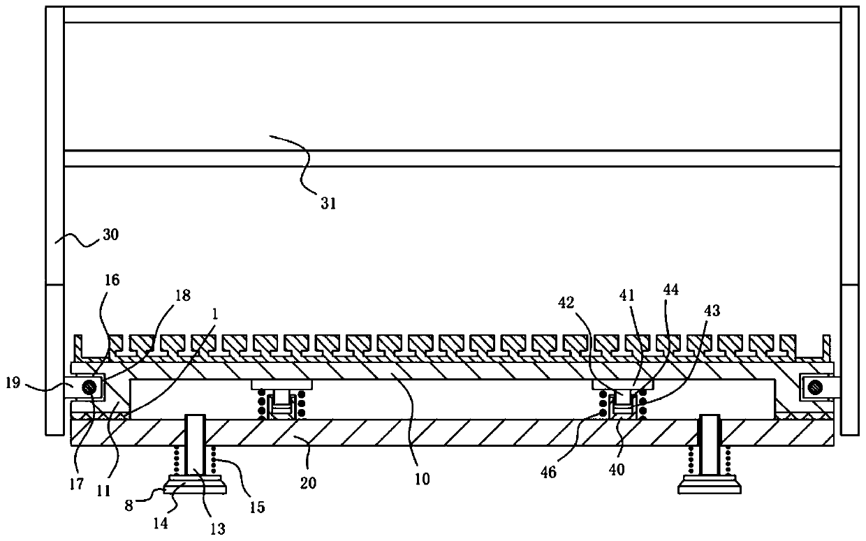
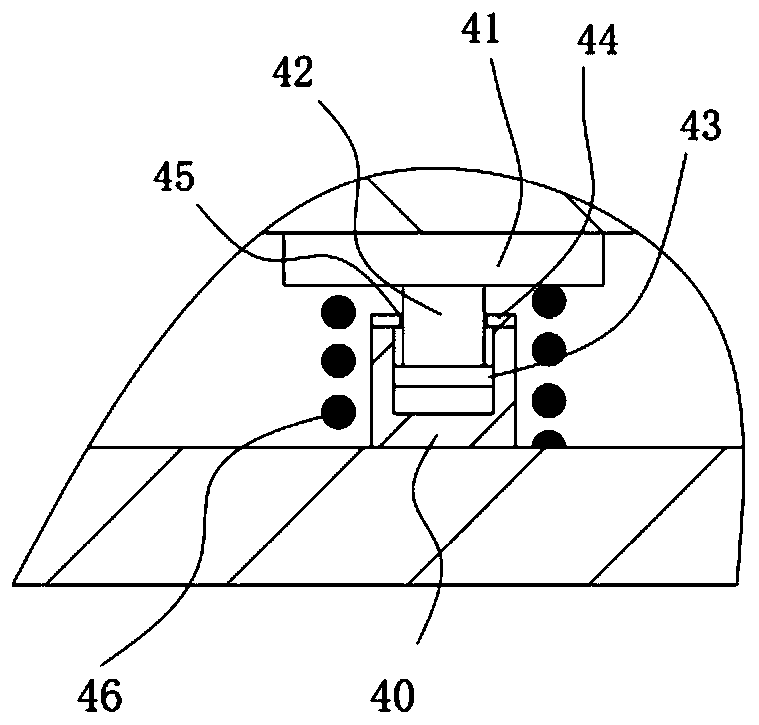
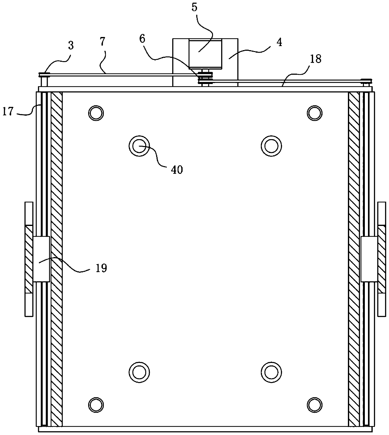
[0020] Example: see Figure 1 to Figure 3 As shown, a machine tool base mechanism of a small precision engraving machine includes a fixed mounting plate 10, the left and right sides of the bottom surface of the fixed mounting plate 10 are formed with downwardly extending extension blocks 11, and the lower buffer connecting plate 20 is in two extensions. Right below the block 11, the vertical screw 13 is screwed into the screw holes provided on the left and right sides of the front and rear of the lower buffer connecting plate 20, and the lower end of the vertical screw 13 extends out of the lower buffer connecting plate 20. The bottom end of the straight screw 13 is fixed with a lower fixed block 14, the buffer spring 15 is inserted and sleeved on the vertical screw 13, the bottom end of the buffer spring 15 is applied to the top surface of the lower fixed block 14, and the top end of the buffer spring 15 is applied to the lower buffer The bottom surface of the connecting plate...


PUM


Abstract

The invention discloses a machine tool base mechanism of a small engraving and milling machine. The mechanism comprises a fixed mounting plate, extending blocks extending downwards are formed at the left side and the right side of the bottom surface of the fixed mounting plate; and a lower buffer connecting plate is located under the two extending blocks. Vertical screw rods are screwed in screw through holes formed in the left and right sides of the front part and the rear part of the lower buffer connecting plate; the lower end of each vertical screw rod extends out of the lower buffer connecting plate, a lower fixing block is fixed to the bottom end of the vertical screw rod, the vertical screw rod is sleeved with a buffer spring in an inserted mode, the bottom end of the buffer springacts force on the top surface of the lower fixing block, and the top end of the buffer spring exerts force on the bottom surface of the lower buffer connecting plate. Thus, through the buffering effect of the buffer spring, an elastic protection plate and a long elastic supporting block, vibration of a machine tool is reduced, noise is lowered, the machining stability is improved, a single drivingmotor is adopted for driving the two long adjusting screw rods to rotate, time synchronization operation is achieved, the installation and adjustment difficulty is low, and the effect is good.

Description

Technical field [0001] The invention relates to the technical field of machine tool equipment, and more specifically to a machine tool base mechanism of a small engraving machine. Background technique [0002] Existing precision engraving machine machine tools generally do not have a buffer mechanism, which will generate a lot of vibration and noise during operation, and it is easy to affect the stability of the equipment; [0003] At the same time, the moving mechanism of the upper support frame of the existing machine tool generally uses two drive screws to rotate to achieve movement, and the two drive screws are driven synchronously by two motors, and the synchronous operation of the two motors requires high synchronization settings and Synchronization makes installation and debugging difficult, and there is still a certain gap between the two. Summary of the invention [0004] The purpose of the present invention is to address the shortcomings of the prior art, and provide a sm...

Claims


Application Information

Patent Timeline
Patent Type & Authority Applications(China)
IPC IPC(8): B23Q1/01
CPCB23Q1/01B23Q1/015
Inventor 温月生
Owner 温月生
Learn More