
Surface cleaning treatment device for cotton cloth production

A technology for surface cleaning and processing equipment, applied in the cleaning method using tools, the cleaning method using liquid, mechanical cleaning, etc., can solve problems such as affecting the beauty of cotton cloth, reducing the quality of cotton cloth, etc., to ensure quality, improve production efficiency, guarantee The effect of cleanliness

Inactive Publication Date: 2020-04-14
义乌市尼美机械加工厂
View PDF0 Cites 4 Cited by
  • Summary
  • Abstract
  • Description
  • Claims
  • Application Information

AI Technical Summary

Problems solved by technology

[0003] During the production and processing of cotton cloth, it is inevitable that some impurities such as dust or lint will stick to it. If the adhered impurities on the surface of the cotton cloth are not cleaned, it will not only affect the appearance of the cotton cloth, but also reduce the quality of the cotton cloth. For fabrics with darker colors, if there are dust, cotton wool and other sundries on the surface, it will be more obvious

Method used


Image

  • Surface cleaning treatment device for cotton cloth production
  • Surface cleaning treatment device for cotton cloth production
  • Surface cleaning treatment device for cotton cloth production

Examples


Embodiment 1

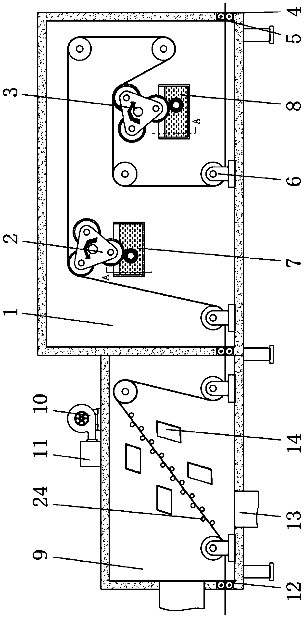
[0031] Embodiment one, with reference to figure 1 and Figure 5 , a kind of surface cleaning treatment equipment for cotton cloth production, comprising wool sticking room 1 dust removal room 9, the side of sticking wool room 1 is provided with dust removal room 9, and the top of dust removal room 9 is provided with blower 10 and air pipe 11, blower 10 and wind The pipe 11 is connected, and the air pipe 11 extends to the inside of the dust removal chamber to communicate with the blowing pipe 14. The bottom surface and the side of the dust removal chamber 9 are provided with a suction port 13, and one side of the dust removal chamber 9 is provided with a feed port 12 below the suction port 13. And feed port 12 one side is provided with and is positioned at dedusting chamber 9 inside and is provided with support bar 24, and sticking wool chamber 1 inside is respectively provided with the first sticking hair group 2, the second sticking wool group 3 and turning roller 6, and the ...

Embodiment 2

[0032] Embodiment two, refer to figure 1 , the supporting rods 24 are provided with a plurality, and the plurality of supporting rods 24 are arranged obliquely, and a plurality of blowing pipes 14 are symmetrically distributed on both sides of the supporting rods 24 arranged obliquely, and the inside of the dust removal chamber 9 is provided with a plurality of supporting rods 24. On the one hand, it can scrape off the larger sticky cotton wool, and on the other hand, it can play an auxiliary role in fixing the cotton cloth, which is conducive to blowing off the dust and other sundries adhered to the surface of the cotton cloth by the blowing pipe 14.

Embodiment 3

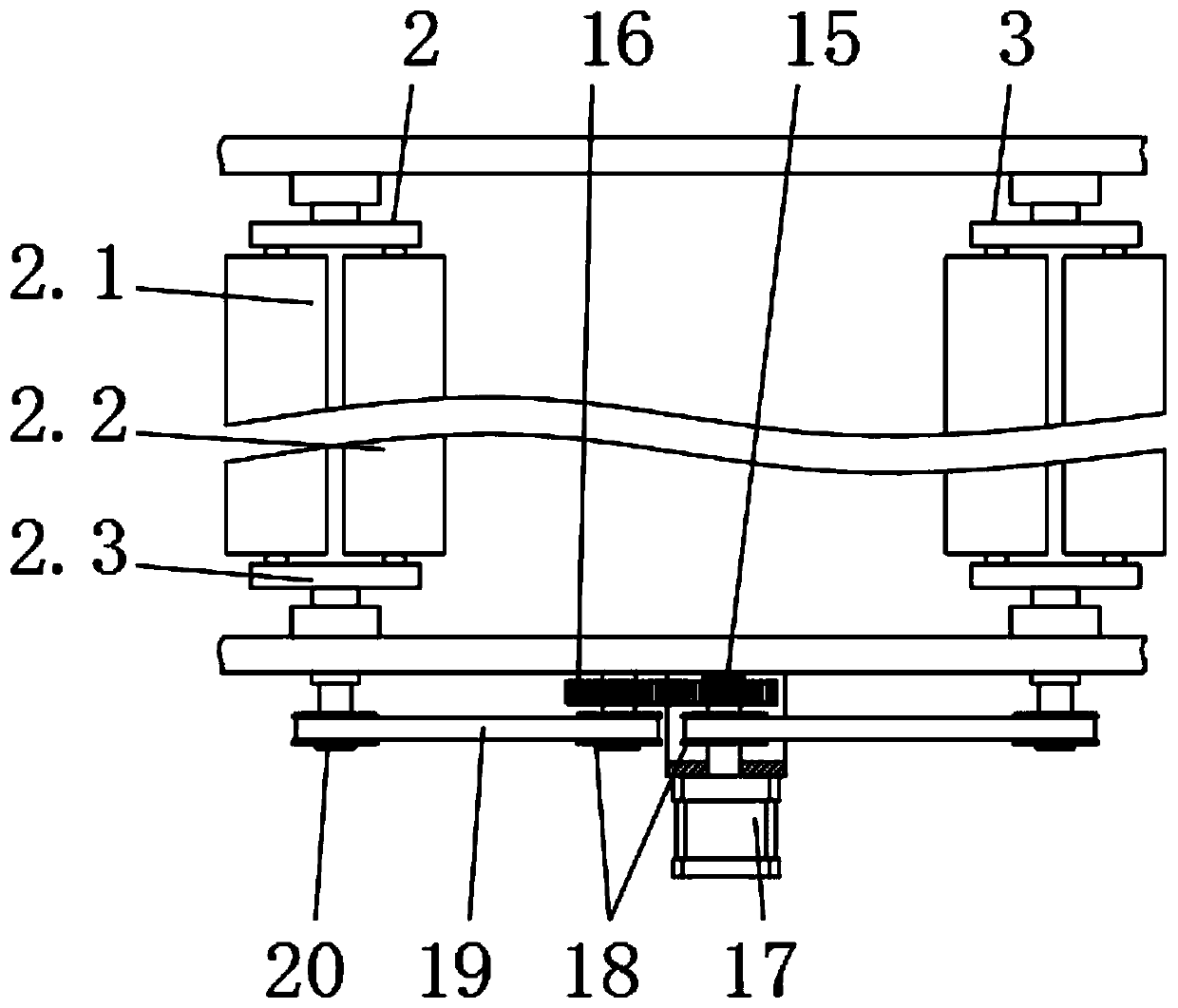
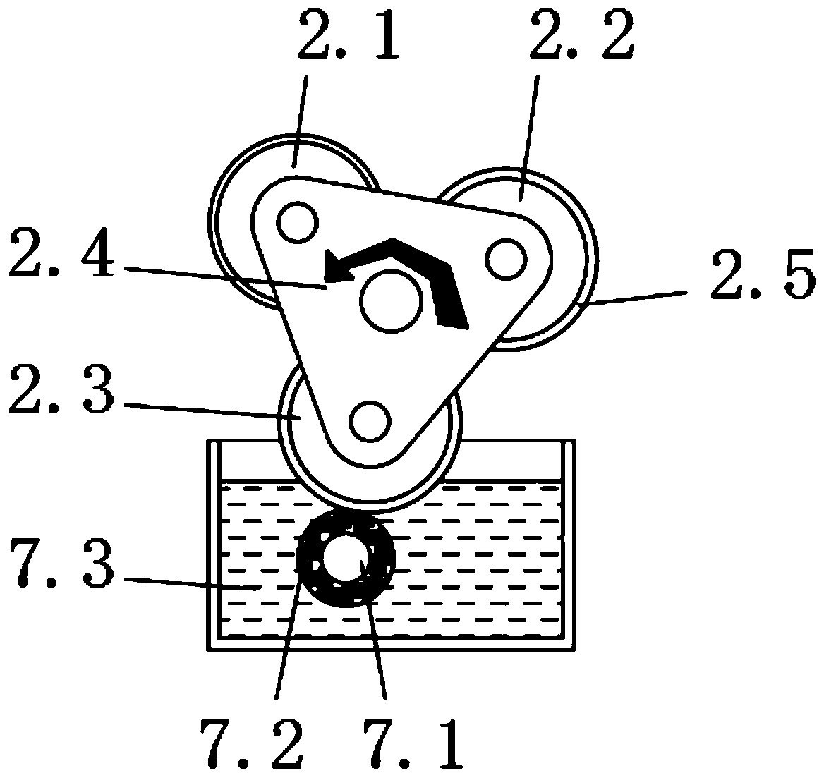
[0033] Embodiment three, refer to Figure 1-3 , the first wool sticking group 2 and the second wool sticking group 3 are composed of the same first wool sticking roller 2.1, second wool sticking roller 2.2, third wool sticking roller 2.3, support plate 2.4, and glue layer 2.5, And the first hair-sticking group 2 and the second hair-sticking group 3 are all installed inside the hair-sticking chamber 1 through the bearing seat, and one end of the first hair-sticking group 2 and the second hair-sticking group 3 extends to the outside of the hair-sticking chamber 1 respectively from the The driving pulley 20 is connected, and the driven pulley 20 side is connected with the driving pulley 18 by sticking the hair belt 19. The driving pulley 18 is provided with two altogether, and the two driving pulleys 18 are respectively connected to the corresponding driving pulley. Gear 15, driven gear 16 keys are connected, and driving gear 15, driven gear 16 meshes are connected, and driving g...


PUM


Abstract

The invention discloses a surface cleaning treatment device for cotton cloth production. The surface cleaning treatment device for cotton cloth production includes a hair collecting chamber and a dustremoval chamber; the dust removal chamber is arranged on one side of the hair collecting chamber, and a blower and an air pipe are arranged on the top of the dust removal chamber; the blower communicates with the air pipe, and the air pipe extends to the interior of the dust removal chamber to communicate with air blowing pipes; and air suction vents are arranged on the bottom and sides of the dust removal chamber. In the invention, the dust removal chamber and the hair collecting chamber are arranged; the cotton cloth to be treated enters and exits the dust removal chamber and the hair collecting chamber in sequence through a feed port, and is wound through a plurality of arranged deflection rollers and then removed from a discharge port; the air is blown by the blower, and the airflow successively enters the plurality of air blowing pipes arranged inside the hair collecting chamber along the air pipe; the dust and cotton debris adhered to the surface of the cotton cloth are blown off through the air blowing pipes, so that the cleanliness of the surface of the cotton cloth is ensured; and a plurality of support rods are arranged inside the dust removal chamber, which can not onlyscrape off the larger cotton debris, but also help to fix the cotton cloth, and is helpful for the air blowing pipes to blow off the dust and other debris adhered to the surface of the cotton cloth.

Description

technical field [0001] The invention relates to the technical field of cotton cloth production and processing equipment, in particular to a surface cleaning treatment equipment for cotton cloth production. Background technique [0002] Cotton is a cloth woven from cotton yarn. It is the general term for all kinds of cotton textiles. Cotton cloth has the characteristics of soft and comfortable to wear, warmth retention, moisture absorption, strong air permeability, and easy dyeing and finishing. Due to its natural characteristics, it has long been loved by people and has become an indispensable basic product in life. It is mostly used to make fashion, casual wear, underwear and shirts. [0003] During the production and processing of cotton cloth, it is inevitable that some impurities such as dust or lint will stick to it. If the adhering impurities on the surface of the cotton cloth are not cleaned, it will not only affect the appearance of the cotton cloth, but also reduc...

Claims


Application Information

Patent Timeline
Patent Type & Authority Applications(China)
IPC IPC(8): D06G1/00B08B1/02B08B3/10B08B13/00B08B1/20
CPCD06G1/00B08B3/10B08B13/00B08B3/041B08B1/143B08B1/20
Inventor 乔辉王起任大龙
Owner 义乌市尼美机械加工厂
Learn More