Protective device for mobile rail transit construction
A technology of moving rails and protective devices, applied in safety devices, mining equipment, earth-moving drilling, etc., can solve the problems of easy height and fall, maintenance personnel falling, life safety threats of maintenance personnel, etc., to increase the acceptance area, reduce effect of risk
- Summary
- Abstract
- Description
- Claims
- Application Information
AI Technical Summary
Problems solved by technology
Method used
Image
Examples
Embodiment 1
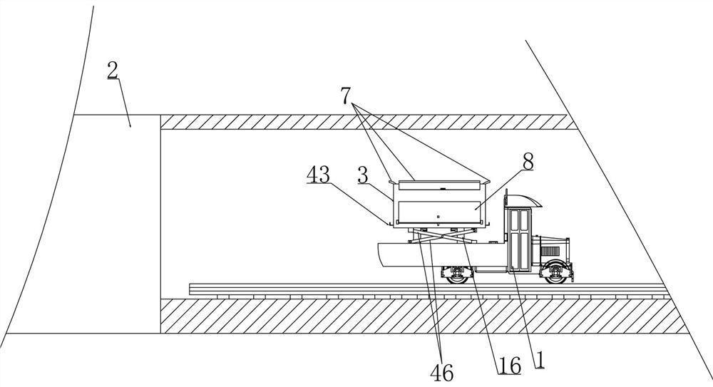
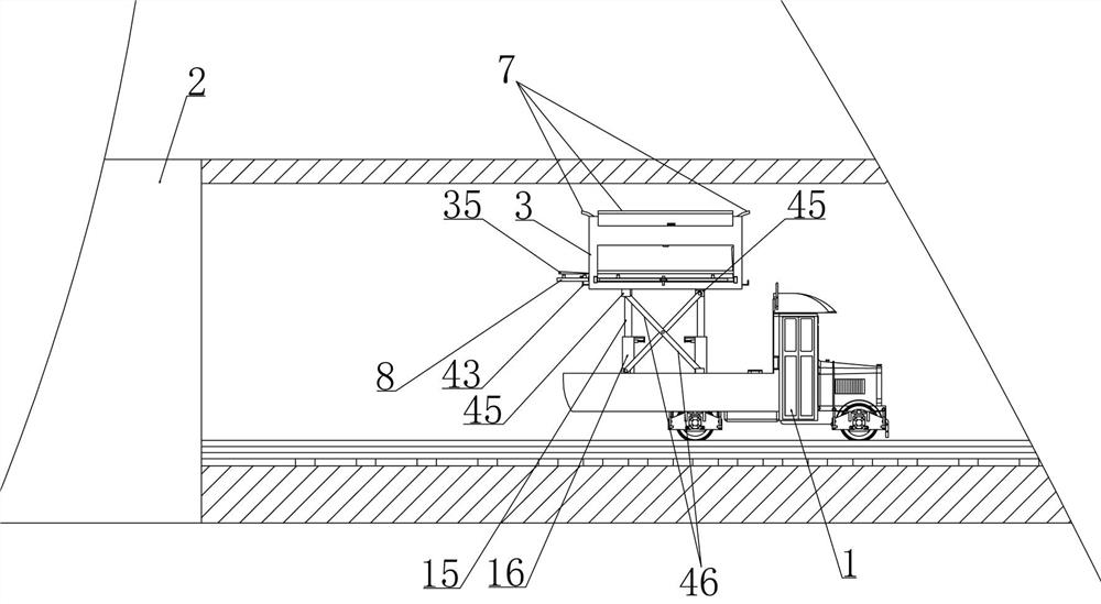
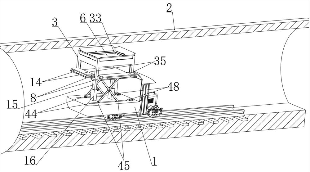
[0044] Embodiment 1, this embodiment provides a kind of protective device for mobile rail transit construction, refer to the attached figure 1 As shown, the track inspection car 1 is included and the inspection box 3 is vertically slidably installed on the track inspection car 1. figure 1 It is a schematic diagram of the track inspection vehicle 1 traveling in the tunnel 2, with figure 2 It is a schematic diagram when the track inspection car 1 is in the maintenance state (at this time, the inspection box 3 is in the raised state), the track inspection car 1 is equipped with a lifting mechanism and the inspection box 3 is lifted by the lifting mechanism, it is characterized in that, refer to the attached Figure 9 As shown, the inspection box 3 is divided into upper and lower two compartments through a partition 5, and the upper end surface of the partition 5 is connected with a vertically sliding bearing plate 6 installed in the inspection box 3 through a telescopic spring 4...
Embodiment 2
[0049] Embodiment 2, on the basis of embodiment 1, with reference to appended Figure 7 As shown, the bottom of the maintenance box 3 is horizontally spaced and fixedly equipped with a slide bar 15 and the track inspection car 1 is equipped with a slide tube 16 that is vertically slidingly matched with the slide bar 15 (the slide bar 15 and the slide tube 16 that cooperate with each other make the overhaul box 3 Move vertically under the action of the lifting mechanism to complete the lifting process of the inspection box 3), refer to the attached figure 2 As shown, a locking block 17 is laterally slid on the sliding tube 16 and a locking hole 18 matching the locking block 17 is provided on the sliding rod 15, and a locking spring 19 is connected between the locking block 17 and the sliding tube 16. A lifting plate 20 is vertically slidably installed in the expansion plate 14, and a lifting spring 21 is connected between the lifting plate 20 and the expansion plate 14. A pres...
Embodiment 3
[0051] Embodiment 3, on the basis of Embodiment 2, how the micro-control processor controls the withdrawal of the locking block 17 from the locking hole 18 that cooperates with it will be described in detail in this embodiment. 17 is connected with the locking spring 19 and one side is fixed with an iron piece and an electromagnet is fixed on the sliding cylinder 16 corresponding to the iron piece. The loop is controlled by a microcontroller processor;
[0052]When the protective device was in a normal state, that is, when the maintenance personnel did not fall, the voltage stabilized power circuit was in a disconnected state under the control of the microcontroller processor, that is, the locking block 17 was not attracted by the magnetic force from the electromagnet (the electromagnet No electricity and no electromagnetic force), when the inspection box 3 is not lifted by the lifting mechanism, the locking block 17 is in contact with the wall of the slide bar 15 that is vert...
PUM
 Abstract
Description
Claims
Application Information
 - R&D
- Intellectual Property
- Life Sciences
- Materials
- Tech Scout
- Unparalleled Data Quality
- Higher Quality Content
- 60% Fewer Hallucinations
Browse by: Latest US Patents, China's latest patents, Technical Efficacy Thesaurus, Application Domain, Technology Topic, Popular Technical Reports.
© 2025 PatSnap. All rights reserved.Legal|Privacy policy|Modern Slavery Act Transparency Statement|Sitemap|About US| Contact US: help@patsnap.com


