
High-protection-level explosive-proof transmission encoder assembly

An encoder and high protection technology, applied in the field of encoder components, can solve the problems of high cost, complex structure, poor coaxiality guarantee, etc., and achieve the effect of improving the explosion-proof level and the protection level.

Pending Publication Date: 2020-04-14
JIAMUSI ELECTRIC MACHINE
View PDF0 Cites 0 Cited by
  • Summary
  • Abstract
  • Description
  • Claims
  • Application Information

AI Technical Summary

Problems solved by technology

When using this structure, the user needs to add a coupling for transmission and a transition flange for positioning between the small shaft of the motor and the small shaft of the encoder. Therefore, there are also complex structures, high costs, and poor coaxiality. Warranty question

Method used


Image

  • High-protection-level explosive-proof transmission encoder assembly

Examples


Embodiment 1

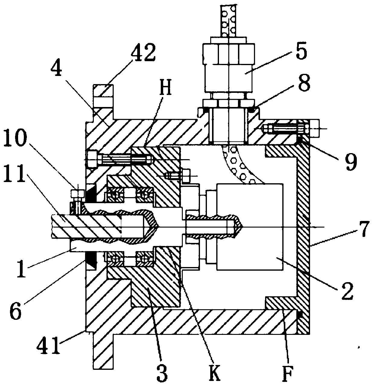
[0013] Embodiment 1: as figure 1 As shown, an encoder assembly of a flameproof transmission with a high protection level includes a transition shaft 1, an encoder 2, a transition sleeve 3, a housing 4 and a flameproof sealing locking joint 5;

[0014] The encoder 2 and the transition bushing 3 are arranged in the housing 4, and the housing 4 is processed with a threaded hole, and the threaded hole on the housing 4 is provided with a flameproof sealing locking joint 5, and the flameproof sealing locking joint 5 is connected with the housing The wires on the encoder 2 pass through the flameproof sealing locking joint 5 to the outside of the housing 4, the transition sleeve 3 and the housing 4 are fixedly connected, and the inside of the housing 4 and the transition sleeve 3 There is a first mating surface H between them, the gap between the first mating surface H of the housing 4 and the first mating surface H of the transition sleeve 3 is 0-0.104mm, and the length of the first ...

Embodiment 2

[0019] Embodiment 2: as figure 1 As shown, the difference between this embodiment and Embodiment 1 is: the side of the transition shaft 1 on the housing 4 in this embodiment is processed with a connecting flange 42, and the connecting flange 42 is provided with a connecting flange 42. The flange 42 is concentric with the positioning boss 41 . The positioning boss 41 is used to ensure that the connection hole 11 is coaxial with the external motor shaft, so as to ensure that the installation accuracy meets the requirements.

Embodiment 3

[0020] Embodiment 3: as figure 1 As shown, the difference between this embodiment and Embodiment 1 is that a sealing groove is processed on the circumference of the threaded hole on the casing 4 in this embodiment, and a first sealing ring 8 is arranged on the sealing groove, and the explosion-proof sealing lock The tight joint 5 is screwed into the thread of the casing 4, and is sealingly engaged with the first sealing ring 8 on the sealing groove.


PUM


Abstract

The invention, which belongs to the technical field of encoders, discloses a high-protection-level flameproof transmission encoder assembly, thereby solving the problems of complex structure, high cost and difficulty in guaranteeing coaxiality because a coupling for transmission and a transition flange for positioning need to be added between a motor small shaft and an encoder small shaft when theexisting encoder is used. The encoder assembly comprises a transition shaft, an encoder, a transition shaft sleeve, a shell and an explosion-proof sealing and locking joint. The encoder and the transition shaft sleeve are arranged in the shell; a threaded hole is formed in the shell; the explosion-proof sealing and locking joint is arranged in the threaded hole in the shell; the explosion-proof sealing and locking joint is in sealing fit with the shell; a wire on the encoder penetrates out of the shell from the explosion-proof sealing and locking joint; the transition shaft sleeve is fixedlyconnected with the shell; a first matching face is arranged between the interior of the shell and the transition shaft sleeve, and the gap between the first matching face of the shell and the first matching face of the transition shaft sleeve is 0 to 0.104 mm. The high-protection-level flameproof transmission encoder assembly is suitable for being used in explosion-proof occasions.

Description

technical field [0001] The invention relates to an encoder assembly, in particular to an encoder assembly for flameproof transmission with high protection level. Background technique [0002] An encoder is a device that compiles and converts signals or data into signal forms that can be used for communication transmission and storage. Applied to the motor, it can be used to detect whether the motor is running according to the direction and speed designed by the system, and it plays a role of monitoring and protection. In recent years, our company's orders for explosion-proof series motors have gradually increased, and users have requested more and more products with explosion-proof encoders. Among the existing encoder manufacturers on the market, there are relatively few manufacturers that can produce explosion-proof encoders, and the models are few and expensive. The flameproof encoders produced by the existing encoder manufacturers actually use the small shaft type non-e...

Claims


Application Information

Patent Timeline
Patent Type & Authority Applications(China)
IPC IPC(8): G01D11/00G01D11/24G01D11/26H02K11/21
CPCG01D11/00G01D11/245G01D11/26H02K11/21
Inventor 孙宝石荆明文李云鹏刘思明胡文华范增谷雨郝家兴李海洋苏立铭刘上一
Owner JIAMUSI ELECTRIC MACHINE
Learn More