Supercharge Your Innovation With Domain-Expert AI Agents!

Crimping machine for power engineering

A technology of electric power engineering and crimping machine, which is applied to circuits, connections, electrical components, etc., can solve the problems of poor crimping effect and inconvenient movement of the crimping machine, and achieves increased stability, convenient movement, and improved extrusion effect. Effect

Active Publication Date: 2021-05-14
STATE GRID SHANDONG ELECTRIC POWER CO LONGKOU POWER SUPPLY CO
View PDF8 Cites 0 Cited by
  • Summary
  • Abstract
  • Description
  • Claims
  • Application Information

AI Technical Summary

Problems solved by technology

[0004] The purpose of the present invention is to solve the disadvantages of the existing crimping machine, first of all, that it is inconvenient to move, and secondly, it simply uses a hydraulic cylinder for one-way punching, and the crimping effect is not good, and the proposed crimping machine for electric power engineering

Method used


Image

  • Crimping machine for power engineering
  • Crimping machine for power engineering
  • Crimping machine for power engineering

Examples


Embodiment 1

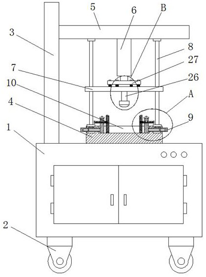
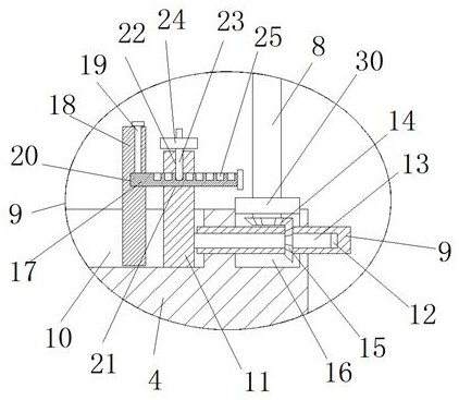
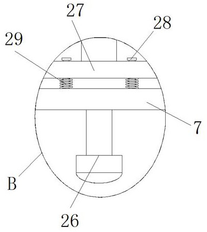
[0030]ReferFigure 1-6, The power engineering crimp, including the body 1, the bottom of the body 1 is fixedly connected to four universal wheel 2, the top of the body 1 is fixedly mounted, and the longitudinal plate 3 is fixed, and the longitudinal plate 3 is fixedly connected with the horizontal plate 5, the horizontal The bottom of the plate 5 is fixedly connected to the hydraulic cylinder 6, and the output shaft of the hydraulic cylinder 6 is fixedly connected to the cushioning mechanism, and the connection plate 7 is fixed to the buffer mechanism, the top of the body 1 is fixedly connected to the processing plate 4, the top of the processing plate 4 The bottom end of the two screws 8 is mounted, and the top end of the two screw bars 8 is rotated from the bottom of the cross plate 5, and the connecting plate 7 is threaded with the two screws 8, and the top of the processing plate 4 is opened. 10. Sliding in the processing tank 10 is mounted with two moving plates 11, and the two ...

Embodiment 2

[0033]ReferFigure 1-6, Power engineering crimping machine, including the body 1, the bottom of the body 1 is fixed by the screw 2 universal wheel 2, and the vertical plate 3 is fixed to the top of the body 1, and the longitudinal plate 3 is fixed by the screw. The plate 5, the bottom of the cross plate 5 is fixed to the hydraulic cylinder 6 by the screw, and the output shaft of the hydraulic cylinder 6 is fixedly connected to the buffer mechanism through the screw, and the buffer mechanism is fixedly connected to the connecting plate 7, the top of the body 1 is passed through the screw. Fixed, the processing plate 4 is fixed, and the top of the processing plate 4 is rotated and mounted with the bottom end of the two screw rods 8, and the top end of the two screw bars 8 is rotated from the bottom of the cross plate 5, the connecting plate 7 and two screw bars 8. The thread is connected, and the machining plate 10 is opened, and the machining tank 10 is slidably mounted with two movin...


PUM


Abstract

The invention belongs to the technical field of electric power engineering equipment, especially a crimping machine for electric power engineering. The existing crimping machine is first of all inconvenient to move, and secondly, it only uses a hydraulic cylinder for one-way punching, and the crimping effect is not good. , the following scheme is proposed, which includes the body, the bottom of the body is fixedly connected with four universal wheels, the top of the body is fixedly installed with a longitudinal plate, one side of the longitudinal plate is fixedly connected with a horizontal plate, and the bottom of the horizontal plate is fixedly connected with a hydraulic cylinder , the output shaft of the hydraulic cylinder is fixedly connected with a buffer mechanism, the buffer mechanism is fixedly connected with a connecting plate, the top of the body is fixedly connected with a processing plate, the top of the processing plate is rotatably installed with the bottom ends of two screw rods, and the two screw rods The tops of both are rotationally connected with the bottom of the horizontal plate, and the connecting plate is threadedly connected with two screw rods. The invention has the advantages of simple structure, convenient operation and convenient movement, can carry out multi-face punching or fixing of parts, and improves the crimping effect.

Description

Technical field[0001]The present invention relates to the technical field of power engineering equipment, and more particularly to a pressing machine for power engineering.Background technique[0002]The crimping machine is a necessary tool for the power industry for wire connection crimping in construction and line maintenance, which can be used to squeeze the two components together. In power engineering applications, the field operation often needs, and The workload is small, so the mobile capability of the crimping machine is high.[0003]The existing pressurizing machine is first moved, followed by a simple and unidirectional stamping using a hydraulic cylinder, and the crimp effect is not good.Inventive content[0004]It is an object of the present invention to solve the existing crimping machine first movement, second only, only a shortcoming of the unidirectional stamping, the crimp effect of the hydraulic cylinder, and the electric power engineering press is used.[0005]In order t...

Claims


Application Information

Patent Timeline
Patent Type & Authority Patents(China)
IPC IPC(8): H01R43/048
CPCH01R43/048
Inventor 高志明徐宁王艳亮林述玲焦艳玲于烜李强孙加军唐兴涛仲丽娜吴红岩杨发亮逄峻王毓英郭乃萌张佳郭蕾
Owner STATE GRID SHANDONG ELECTRIC POWER CO LONGKOU POWER SUPPLY CO
Features
  • R&D
  • Intellectual Property
  • Life Sciences
  • Materials
  • Tech Scout
  • Unparalleled Data Quality
  • Higher Quality Content
  • 60% Fewer Hallucinations
Learn More