A radio system electromagnetic interference testing system and method

A radio system and electromagnetic interference technology, applied in transmission systems, electrical components, transmission monitoring, etc., can solve problems such as high uncertainty of test results, high test difficulty, and complicated test schemes, so as to achieve simple test schemes and reduce test difficulty , the effect of reducing computational complexity

Active Publication Date: 2022-03-08
广电计量检测(成都)有限公司 +1
View PDF7 Cites 0 Cited by
  • Summary
  • Abstract
  • Description
  • Claims
  • Application Information

AI Technical Summary

Problems solved by technology

At present, the test scheme of the transmission system is relatively complicated, and there are many test equipment used, and there are various types of electromagnetic interference in the wireless communication system, which makes the test difficult and the uncertainty of the test results is high.

Method used


Image

  • A radio system electromagnetic interference testing system and method
  • A radio system electromagnetic interference testing system and method

Examples


Embodiment 1

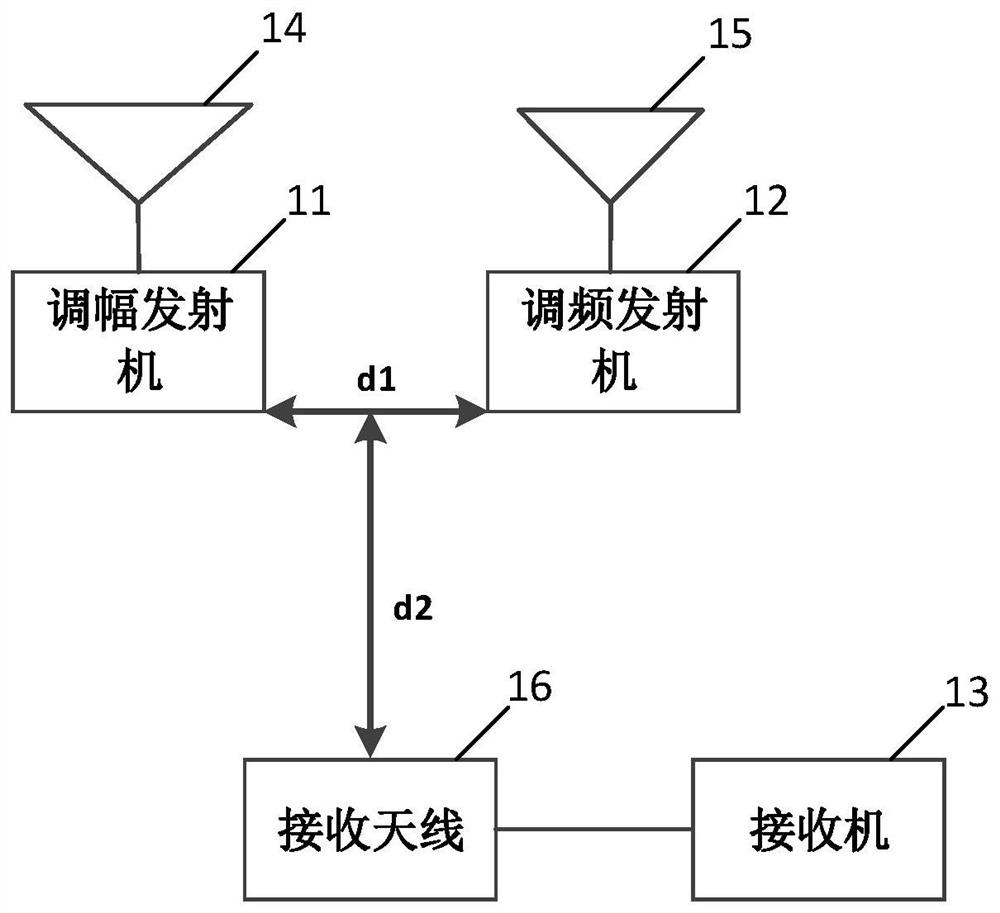
[0026] see figure 1 It is a schematic structural diagram of a radio system electromagnetic interference testing system provided in Embodiment 1 of the present invention, including:

[0027] Installed in a semi-anechoic chamber, including: AM transmitter 11, FM transmitter 12, receiver 13, first transmitting antenna 14, second transmitting antenna 15 and receiving antenna 16;

[0028] The first transmitting antenna 14 is connected to the AM transmitter 11, the second transmitting antenna 15 is connected to the FM transmitter 12, and the receiving antenna 16 is connected to the receiver 13;

[0029] The AM transmitter 11 communicates with the receiver 13 through the first transmitting antenna 14 and the receiving antenna 16, and the FM transmitter 12 communicates with the receiver 13 through the second transmitting antenna 15 and the receiving antenna 16. The receiver 13 is connected in communication;

[0030] The AM transmitter 11 is installed at a first preset distance from ...

Embodiment 2

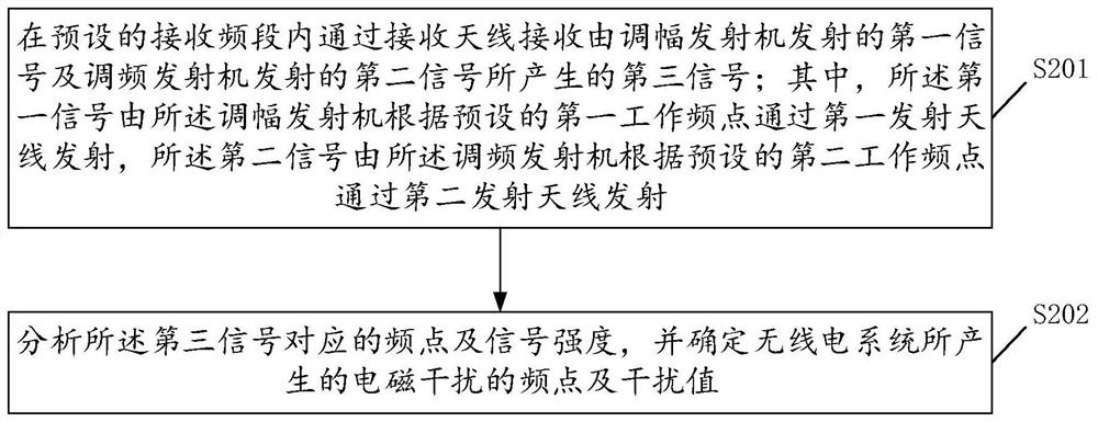
[0038] see figure 2 , is a schematic flowchart of a radio system electromagnetic interference testing method provided in Embodiment 2 of the present invention, and the method includes steps S201 to S202.

[0039] S201. Receive the third signal generated by the first signal transmitted by the AM transmitter and the second signal transmitted by the FM transmitter through the receiving antenna in the preset receiving frequency band; wherein, the first signal is transmitted by the AM transmitter The transmitter transmits through the first transmitting antenna according to the preset first operating frequency, and the second signal is transmitted by the FM transmitter through the second transmitting antenna according to the preset second operating frequency.

[0040] In the above embodiment, preferably, before step S201, it also includes:

[0041] Determine the main operating frequency point, transmission power and communication distance of the AM transmitter, and set the first o...


PUM


Abstract

The invention discloses a radio system electromagnetic interference testing system, which is installed in a semi-anechoic chamber and includes: an AM transmitter, a FM transmitter, a receiver, a first transmitting antenna, a second transmitting antenna and a receiving antenna; the first transmitting antenna It is connected with the AM transmitter, the second transmitting antenna is connected with the FM transmitter, and the receiving antenna is connected with the receiver; the AM transmitter is connected with the receiver through the first transmitting antenna and receiving antenna, and the FM transmitter is connected through the second transmitting antenna, receiving The antenna is communicatively connected to the receiver; the AM transmitter is installed at a first preset distance from the FM transmitter, and the receiving antenna is set at a second preset distance from the AM transmitter to the FM transmitter. The invention also discloses a radio system electromagnetic interference test method, which can effectively eliminate other electromagnetic interference existing in the space, reduce hardware requirements of test equipment, thereby effectively reducing test difficulty and improving test result accuracy.

Description

technical field [0001] The invention relates to the technical field of wireless communication, in particular to a radio system electromagnetic interference testing system and method. Background technique [0002] With the rapid development of information construction, different electromagnetic interferences will be caused between radio equipment, and the radio equipment is developing in the direction of intelligence, integration, and complexity, so the problem of electromagnetic interference is very serious; modulation is very important in radio communication. It is important to study the problem of electromagnetic interference between transmitting devices of different modulations. At present, the test scheme of the transmission system is relatively complicated, and there are many test equipment used, and there are various types of electromagnetic interference in the wireless communication system, which makes the test difficult and the uncertainty of the test results is high...

Claims


Application Information

Patent Timeline
Patent Type & Authority Patents(China)
IPC IPC(8): H04B17/345H04B17/391
CPCH04B17/345H04B17/3912
Inventor 王媛
Owner 广电计量检测(成都)有限公司
Why Eureka
Try Eureka