Novel cross bar fixing support of hanging net

A technology for fixing brackets and beams, applied in the application, poultry industry, poultry cages or houses, etc., to avoid easy rust, avoid welding process, and improve the service life.

Active Publication Date: 2020-04-17
四川金仕达自动化设备有限公司
View PDF2 Cites 0 Cited by
  • Summary
  • Abstract
  • Description
  • Claims
  • Application Information

AI Technical Summary

Problems solved by technology

[0004] The present invention provides a new type of fixed bracket for hanging net beams. The beams and longitudinal bars are connected in a non-welding manner to improve the service life of the brackets and solve the problems mentioned in the background technology above.

Method used


Image

  • Novel cross bar fixing support of hanging net
  • Novel cross bar fixing support of hanging net
  • Novel cross bar fixing support of hanging net

Examples


Embodiment 1

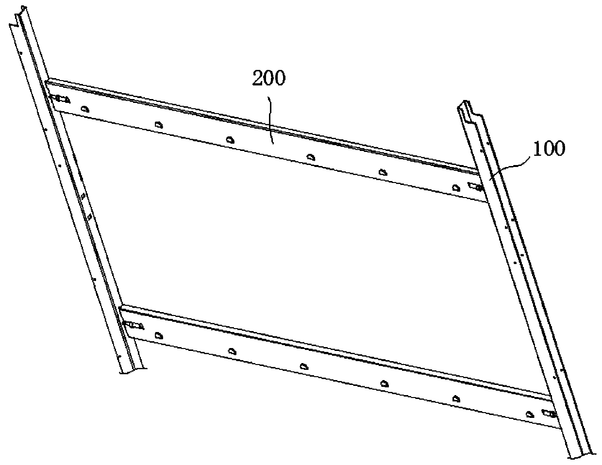
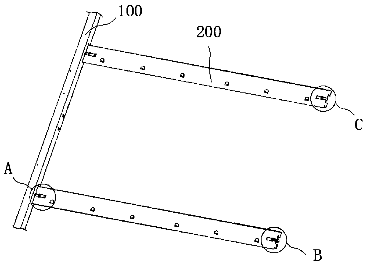
[0026] see figure 1 Or 6, the support is composed of two vertical longitudinal bars 100 and a plurality of cross beams 200, similar to a ladder, the two longitudinal bars 100 are parallel to each other, the cross beam 200 is perpendicular to the longitudinal bars 100 and the two ends of the cross beam 200 are respectively connected to two The longitudinal bars 100 are connected, the cross beam 200 is a rectangular steel plate structure, and the longitudinal bar 100 is a steel structure with a U-shaped cross section processed by steel plates.

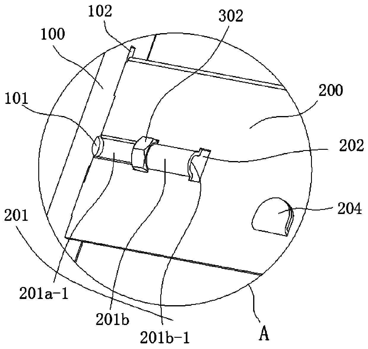
[0027] see Figure 6-7 , the outer surface of the crossbeam 200 is provided with a hook 204, the hook 204 is used to hang the cage of the poultry, it should be noted that the hook 204 is formed by the stamping process of the crossbeam 200, in order to form the hook 204, the inside of the crossbeam 200 forms a stamping groove 204 a , the hook 204 formed by stamping has better durability than the hook 204 welded on the beam 200 , and the ...

Embodiment 2

[0039] In the above embodiment, the beam 200 is subjected to a large thrust, and the direction of the thrust is from the opening direction of the positive groove 201a-1 to the opening direction of the reverse groove 201b-1, and the effect of the force is to make the bolt 301 move away from the positive The opening direction of the groove 201a-1 or the reverse groove 201b-1 moves, especially when the distance between the positive concave ring 201a and the reverse concave ring 201b is too large, the position where the crossbeam 200 contacts the longitudinal bar 100 will slide, thereby The bolt 301 may rotate with the nut 302 as the axis due to the force and directly break away from between the positive concave ring 201a and the reverse concave ring 201b, thus causing the phenomenon that the beam 200 and the vertical rod 100 are not fixed stably. The above problems In this embodiment, a hanging plate 203 is added at one end of the beam 200, and the hanging plate 203 is clamped wit...

Embodiment 3

[0052] Such as Figure 4-6 , in the above-mentioned embodiment, when the longitudinal bar 100 moves away from the cross beam 200, the bolt 301 plays the main role of connecting and fixing, but if things go on like this, the bolt 301 is easy to rotate relative to the nut 302, thus causing the gap between the cross beam 200 and the longitudinal bar 100 In order to solve the above problem, the hanging plate 203 is arranged in an L-shape in this embodiment, and the L-shaped hanging plate 203 is divided into a fixed end 203a and an extension end 203b. The fixed end 203a is a rectangular steel plate structure, and the fixed end 203a is fixed to one end of the crossbeam 200, the extension end 203b is fixed to one side of the fixed end 203a, and there is a gap between the side of the extension end 203b close to the crossbeam 200 and the crossbeam 200, the narrowest part of the gap The width of the beam is the same as the thickness of the steel plate of the longitudinal bar 100, and th...


PUM


Abstract

The invention relates to the technical field of cages of cultivation equipment and discloses a novel cross bar fixing support of a hanging net. The cross bar fixing support comprises longitudinal rodsand cross bars, wherein the longitudinal rods and the cross bars are connected; one end of each cross bar is fixed on the longitudinal rods through fixing bolts; a sleeve is arranged at one end of each cross bar, and the fixing bolts are arranged in the respective sleeve; and the cross bars and the longitudinal rods are fixed through the fixing bolts. According to the novel cross bar fixing support of a hanging net, bolt holes are formed inside the longitudinal rods, a forward groove and a reverse groove are formed in one end of each cross bar by a stamping mode, and nuts are placed in the gaps between the forward grooves and the reverse grooves; and the bolts sequentially run through the bolt holes, the forward grooves, the nuts and the reverse grooves, so that the cross bars and the longitudinal rods can be fixed. By the fixing mode, occurrence of the soldering process can be completely avoided, and the service life of the fixing support can be prolonged.

Description

technical field [0001] The invention relates to the technical field of aquaculture equipment cages, in particular to a novel fixed bracket for hanging net beams. Background technique [0002] Nowadays, the aquaculture industry is booming, and the breeding methods are becoming more and more modern. The poultry breeding method is more to put poultry in cages for breeding. In order to save space, the cages for raising poultry will be hung on two brackets from bottom to top. between, and the existing support is composed of two vertical longitudinal bars and a plurality of beams, similar to a ladder, the two longitudinal bars are parallel to each other, the beams are perpendicular to the longitudinal bars and the two ends of the beam are respectively connected to the two longitudinal bars At the same time, a hook is provided on the outer surface of the beam, and the hook is used for hanging cages for breeding poultry. [0003] Since the beams and longitudinal bars are all steel ...

Claims


Application Information

Patent Timeline
Patent Type & Authority Applications(China)
IPC IPC(8): A01K31/00
CPCA01K31/002
Inventor 殷光兵江洪江勇
Owner 四川金仕达自动化设备有限公司
Why Eureka
Try Eureka