
Conductive dust suction pipe capable of being bent bidirectionally

A technology for suction tubes and tube segments, applied in the field of conductive vacuum tubes, which can solve problems such as difficult cleaning, volume reduction, and high safety risks, and achieve the effects of reducing the burden of manual cleaning, avoiding bending, and convenient operation

Pending Publication Date: 2020-04-17
邬永龙
View PDF0 Cites 1 Cited by
  • Summary
  • Abstract
  • Description
  • Claims
  • Application Information

AI Technical Summary

Problems solved by technology

[0002] Vacuum cleaners are a widely used cleaning and sanitary appliance, used to remove dust from floors, carpets, walls, furniture, clothing and various gaps. Vacuum cleaners generally include a long suction pipe, but as a This kind of rigid component is difficult to bend. When cleaning low places such as the bottom of the bed and the bottom of the table, the vacuum tube cannot directly go deep into the bottom area for cleaning. It requires people to bend down or squat down to reach the floor brush into the bottom, which increases human strength. Consumption and labor intensity, especially for some people with unchanged lumbar spine or elderly people, it is very difficult to clean, and when cleaning the bottom of the bed and the bottom of the table, the vacuum tube is easy to collide with objects, damage the edge of the object, affect the appearance and damage the vacuum tube When cleaning the door frame, the top of the cabinet and other high places that are hard to reach, it is more difficult to bend the vacuum tube to vacuum the high place, which brings great inconvenience to daily cleaning
[0003] At present, some vacuum cleaners that can be bent have also appeared. The patent document No. 209186556 discloses a vacuum cleaner and its bendable connecting pipes, including upper and lower joint pipes that can be bent and moved closer to each other, reducing the length. It is convenient for storage, and the vacuum cleaner can be lifted by the handle, which is more convenient to carry and improves the user experience; however, this patent document only bends the vacuum tube to the folded state at one time to reduce the volume and save space, and cannot pass through the vacuum during the vacuuming process. Bend to clean under the bed, under the table or high places that are difficult to clean;
[0004] The patent document with the notification number 209186550 discloses a hand-held vacuum cleaner, by setting the pivot used to hinge the upper rod section and the lower rod section on the front side wall of the rod, and the lock hook in the locking mechanism is arranged on the rear of the rod On the side wall, the unlocking switch in the locking mechanism is set on the front side wall of the rod, so as to facilitate manual operation. Through the linkage parts, the unlocking switch on the front side of the rod and the lock hook on the rear side of the rod form a linkage relationship, that is, the front unlocking After the switch is operated, the locking hook on the rear side is unlocked, which makes it easier for users to operate the handheld vacuum cleaner in this case; however, the patent document only achieves bending through the deformation of the flexible tube, and cannot fix the bending angle. When it is in a place that is difficult to reach, it is difficult for the lower pipe section to droop and the drooping section is free to sway, and the bending angle cannot be fixed, so it is difficult to achieve dust suction, and there is also a greater safety risk

Method used


Image

  • Conductive dust suction pipe capable of being bent bidirectionally
  • Conductive dust suction pipe capable of being bent bidirectionally
  • Conductive dust suction pipe capable of being bent bidirectionally

Examples


Embodiment Construction

[0035] In order to facilitate the understanding of the present invention, the present invention will be described more fully below with reference to the relevant drawings, in which several embodiments of the present invention are shown, but the present invention can be realized in different forms, and is not limited to the text described On the contrary, these embodiments are provided to make the disclosure of the present invention more thorough and comprehensive.

[0036] It should be noted that when an element is said to be "fixed on" another element, it can be directly on the other element or there can be an intervening element, and when an element is said to be "connected" to another element, it can be Directly connected to another element or possibly intervening elements at the same time, the terms "vertical," "horizontal," "left," "right," and similar expressions are used herein for purposes of illustration only.

[0037] Unless otherwise defined, all technical and scien...


PUM


Abstract

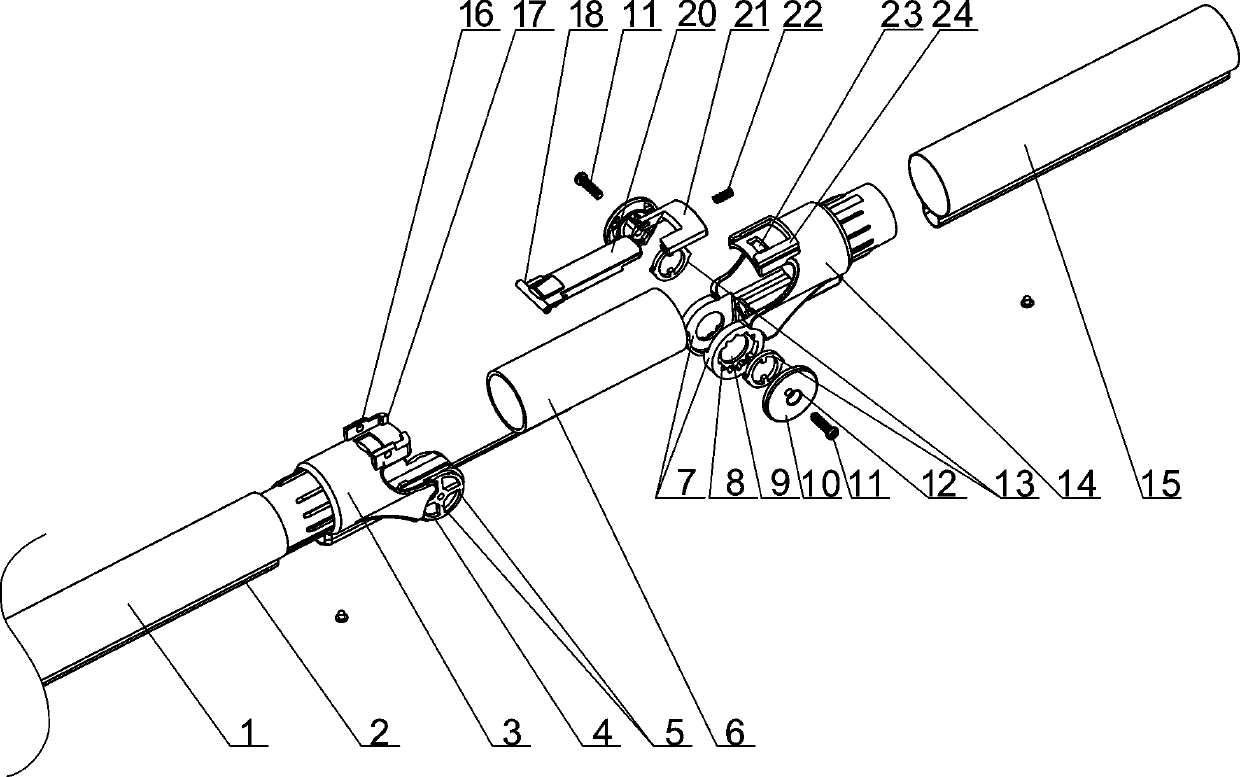
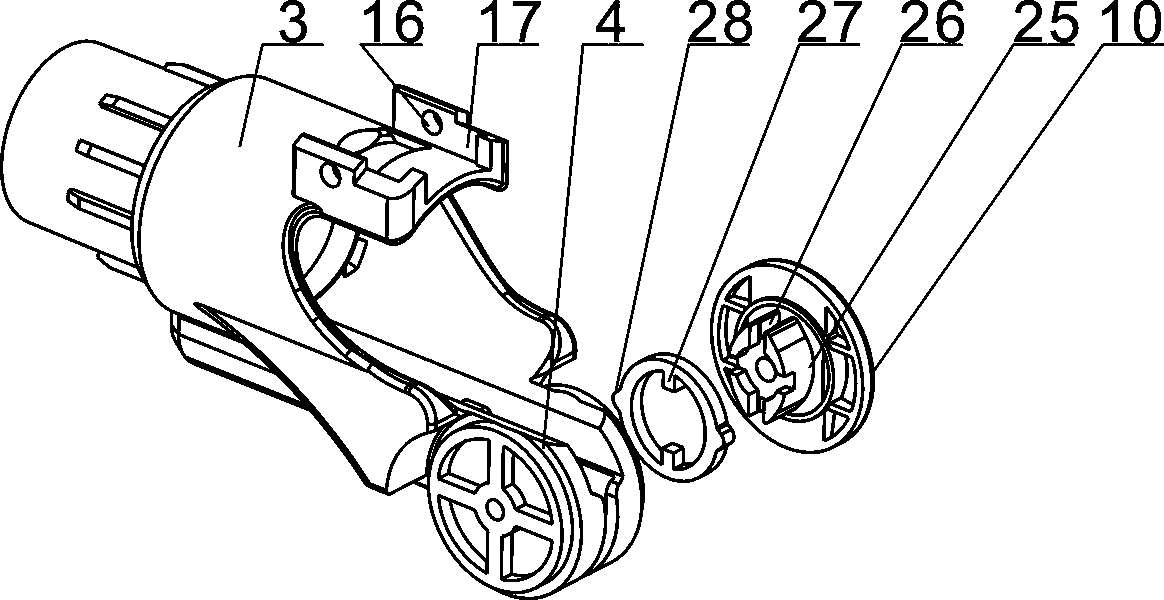
The invention provides a conductive dust suction pipe capable of being bent bidirectionally. The conductive dust suction pipe comprises a dust suction pipe body, a fixed joint (3), a spring hose (6) and a rotary joint (14). The dust suction pipe body comprises an upper pipe section (1) and a lower pipe section (15). One end of the upper pipe section (1) is a free end; the fixed joint (3) is sleeved in the other end of the upper pipe section (1); one end of the lower pipe section (15) is connected with a dust collector floor brush in a matching mode; and the rotary joint (14) is sleeved in theother end of the lower pipe section (15). A fixed base (4) extending out of the front portion of the fixed joint (3) is clamped between two rotary shaft bases (7) extending out of the front portion ofthe rotary joint (14). The upper pipe section and the lower pipe section of the dust suction pipe are rotationally connected through a rotating shaft, limiting type two-way bending in the range of 0-90 degrees upwards and 0-180 degrees downwards can be realized; the cleaning and dust suction requirements under different situations can be met by conducting limiting type bending deformation on thedust suction pipe; and the operation is convenient and fast, and manpower and material resource consumption is reduced.

Description

technical field [0001] The invention mainly relates to the technical field of dust suction tubes for vacuum cleaners, in particular to a bidirectionally bendable conductive dust suction tube. Background technique [0002] Vacuum cleaners are a widely used cleaning and sanitary appliance, used to remove dust from floors, carpets, walls, furniture, clothing and various gaps. Vacuum cleaners generally include a long suction pipe, but as a This kind of rigid component is difficult to bend. When cleaning low places such as the bottom of the bed and the bottom of the table, the vacuum tube cannot directly go deep into the bottom area for cleaning. It requires people to bend down or squat down to reach the floor brush into the bottom, which increases human strength. Consumption and labor intensity, especially for some people with unchanged lumbar spine or elderly people, it is very difficult to clean, and when cleaning the bottom of the bed and the bottom of the table, the vacuum t...

Claims


Application Information

Patent Timeline
IPC IPC(8): A47L9/24
CPCA47L9/24A47L9/248
Inventor 邬永龙
Owner 邬永龙
Learn More